


Disassembly
Remove the oil pump cover
Remove the inner and outer rotors.
Remove the plug and plunger spring.
Remove the control plunger.
Remove the oil pump housing.
Examination
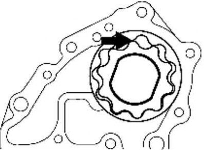
Fig. 2.298. Measuring the gap between the inner and outer rotors
Measure the gap between the inner rotor and the outer rotor using a feeler gauge (fig. 2.298).
If the gap value exceeds the maximum value, replace the inner rotor, outer rotor, or both rotors.
- Standard gap between tooth heads: 0.18 mm.
- Maximum clearance between tooth heads: 0.20 mm.
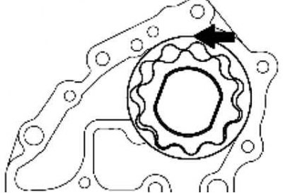
Fig. 2.299. Measuring the gap between the outer rotor and the housing
Measure the gap between the outer rotor and the housing using a feeler gauge (fig. 2.299).
If the clearance value exceeds the maximum value, replace the outer rotor, oil pump housing, or outer rotor with housing.
- Standard gap: 0.175 mm.
- Maximum gap: 0.20 mm.
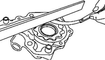
Fig. 2.300. Measuring the lateral clearance of the oil pump housing
Measure the side clearance using a feeler gauge (fig. 2.300).
If the clearance value exceeds the maximum value, replace the inner rotor, oil pump housing, or the inner rotor with housing.
- Standard side clearance: 0.03–0.07 mm.
- Maximum side clearance: 0.09 mm.
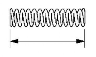
Fig. 2.301. Measuring the length of the plunger spring
Measure the free length of the plunger spring using a vernier caliper (fig. 2.301).
The article is reprinted from the portal (Mazbook)
If the length is not within specification, replace the plunger spring.
Length of plunger spring in free state: 45.94 mm.
Assembly
Install the oil pump housing.
Install the control plunger, plunger spring and plug.
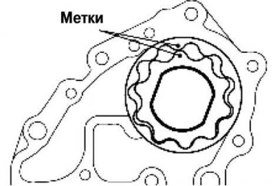
Fig. 2.302. Alignment of marks on inner and outer rotors
Align the marks on the inner and outer rotors and assemble them (fig. 2.302).
Install the rotors and oil pump cover.