


Removal and installation the oil pump
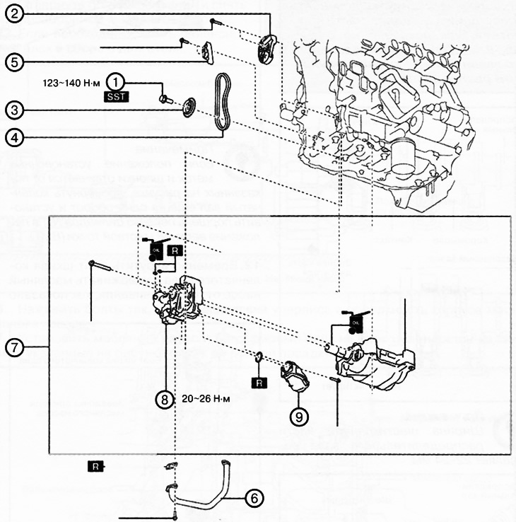
Diesel engine:
1. Oil pump sprocket mounting bolt.
2. Oil pump drive chain tensioner.
3. Oil pump sprocket.
4. Oil pump drive chain.
5. Oil pump drive chain tensioner.
6. Oil pipe.
7. Balance block assembly.
8. Oil pump.
9. Oil intake.
Note.
: replace the part with a new one after each removal.
: use a special tool or device.
: apply oil.
Attention.
- A hot engine and engine oil can cause various burns. It is necessary to turn off the engine and wait until it cools down.
- A vehicle raised on a lift but not supported by safety stands is dangerous. It may jump off and fall, causing death or serious injury. Do not work around or under a raised vehicle that is not supported by safety stands.
- Prolonged skin contact with used motor oil can cause skin cancer. Wash your hands thoroughly with soap and water immediately after handling motor oil.
- If the camshaft is rotated after the drive chain is removed, the valves may hit the piston crown when the piston is at top dead center, causing engine damage. When rotating the camshaft with the drive chain removed, all pistons in the engine must be set to the middle position.
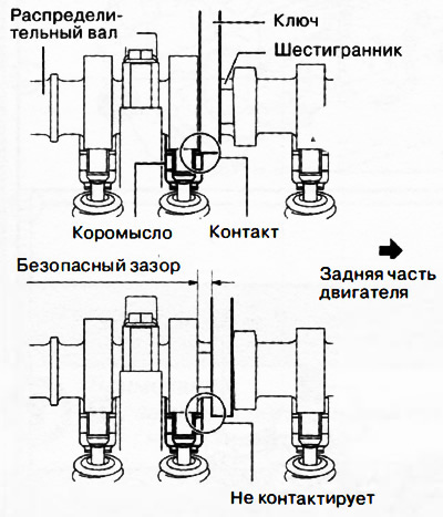
- When turning the camshaft with a wrench on the hexagonal part, the wrench may hit the rocker arm and damage it. To prevent damage to the rocker arm, when holding the camshaft by the hexagonal part, place the wrench closer to the rear of the engine, as shown in the figure, to ensure a safe gap between the wrench and the camshaft lobe.
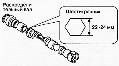
Note: The width of the hexagonal part of the camshaft is 22-24 mm.
Removal the oil pump
1. Disconnect the negative battery terminal.
2. Remove the decorative engine cover.
3. Remove engine oil pan No.2.
4. Remove the mudguard.
5. Remove the accessory drive belt.
6. Drain the engine oil.
7. Remove the oil pan from the engine.
8. Remove the fuel injectors.
9. Drain the coolant.
10. Remove the timing chain (see chapter "Mechanical part of the 2.2L diesel engine").
11. Make sure that the timing marks of the oil pump drive sprockets and the key are in the positions shown in the figure.
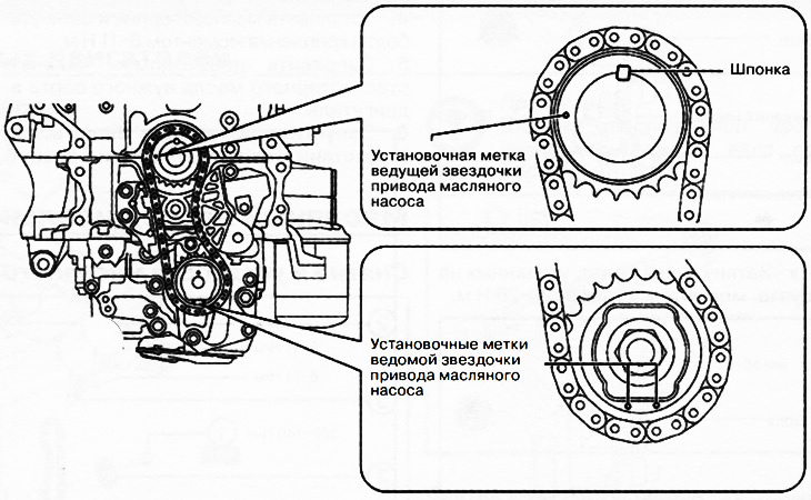
Note: If the position of the timing marks and key differs from those shown in the figure, turn the crankshaft one more revolution and set the piston of the first cylinder No.1 to the top dead center (TDC) position.
12. Temporarily tighten the crankshaft pulley bolt and hold the oil pump from turning as shown in the figure.
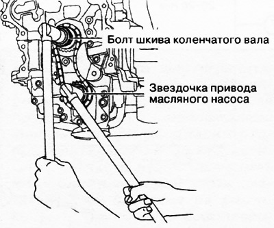
13. Loosen the oil pump sprocket mounting bolt.
Note: At this stage, you only need to loosen the sprocket mounting bolt, but do not unscrew it completely. Unscrew the bolt after removing the oil pump drive chain tensioner.
14. Insert a flat-head screwdriver wrapped in cloth into the gap between the protrusion at the bottom of the cylinder block and the oil pump chain, as shown in the figure.
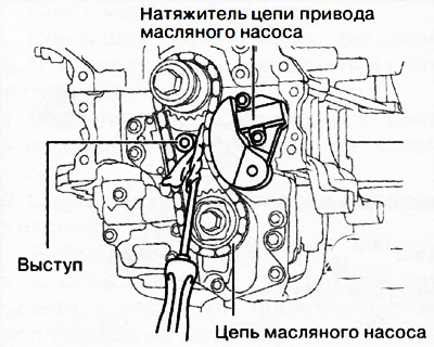
15. Moving the screwdriver in the direction of the arrow, press the oil pump drive chain and press the plunger of the oil pump drive chain tensioner.
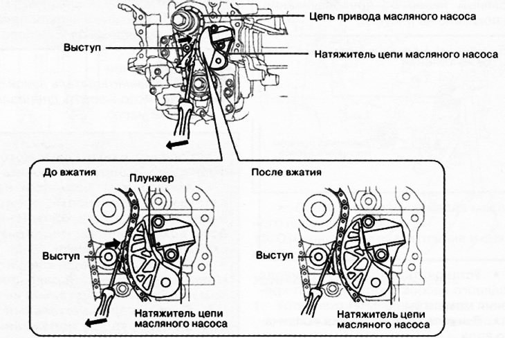
16. Press the plunger and insert a wire with a diameter of approximately 1.4 mm or a rolled-up piece of paper into the hole in the oil pump chain tensioner housing.
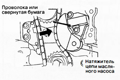
Note: The wire or rolled up paper will hold the plunger in place, which will take the tension off the drive chain.
17. Remove the oil pump chain tensioner.
18. Remove the drive chain with the oil pump sprocket as one unit.
19. Unscrew the temporarily installed crankshaft pulley bolt.
20. Remove the oil pump drive chain tensioner.
21. Loosen the mounting bolts and remove the oil pipe.
22. Loosen the mounting bolts and remove the oil intake from the oil pump.
23. If necessary, remove the balancer block assembly from the engine.
Installing an oil pump
Attention.
- If the balance shaft splines (No. 1) are damaged, the engagement with the oil pump gear will be disrupted, which may make it impossible to install the oil pump. Be careful not to damage the balance shaft splines.
- Since the balance shaft journal (No. 1) rotates with the oil pump bearing, if the journal is damaged, the bearing may also be damaged. Be careful not to damage the balance shaft journal.
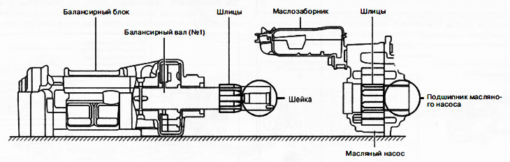
1. Apply clean engine oil to the new oil pickup O-ring.
2. Install the oil pickup onto the oil pump.
3. Make sure that the alignment pin of the balance shaft (No. 1) is perpendicular to the mounting surface of the cylinder block. If the alignment pin position is different, turn the balance shaft (No. 1) to adjust the position.
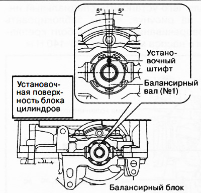
4. Apply engine oil to the surface of the balance shaft journal (No. 1).
5. Align the height of the balance shaft splines (No. 1) with the splines of the oil pump and install the oil pump on the balance block.
Note: There is no need to align the splines of the balance shaft (No. 1) and the oil pump in any strictly defined position.
6. Tighten the bolts so that their heads rest against the surface of the oil pump housing.
7. Install the oil pump and balancer block on the cylinder block and tighten the bolts shown in the figure until they are fully seated.
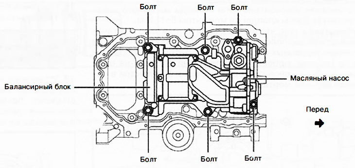
8. Tighten the oil pump mounting bolts in the sequence shown in the figure to a torque of 20-26 Nm.
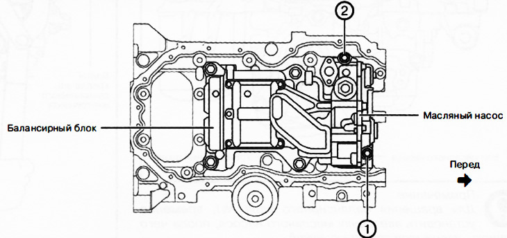
9. Tighten the balance block mounting bolts in two stages in the sequence shown in the figure:
- Stage 1: 16-22 Nm.
- Stage 2: 30-36 Nm.
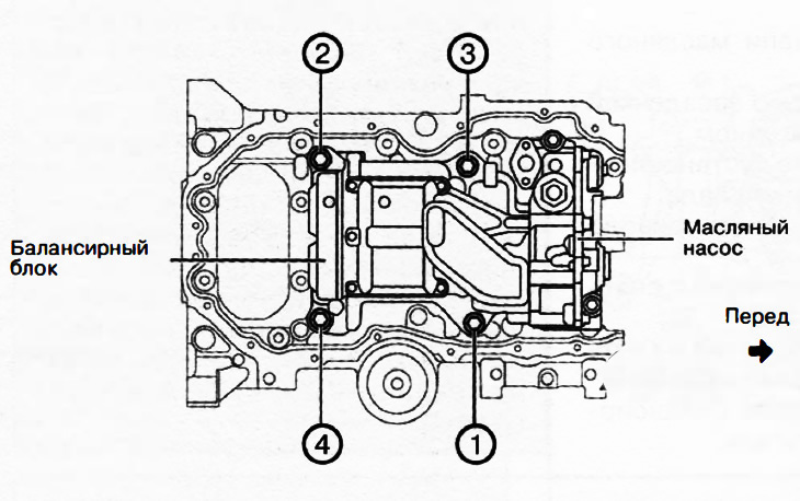
10. Tighten the oil pump mounting bolts in the sequence shown in the figure to a torque of 20-26 Nm.
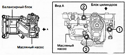
11. Install the oil pipe with new gaskets and tighten the mounting bolts to 10-13 Nm.
12. Install the oil pump drive chain tensioner and tighten the mounting bolts to a torque of 8-11 Nm.
13. Make sure that the crankshaft key and dowel pin are positioned as shown in the figure. If the position of the specified elements differs from that shown in the figure, turn the crankshaft one more revolution to set the piston of the first cylinder to the top dead center position.
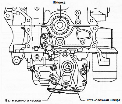
Note: To rotate balance shaft No.1, temporarily install the oil pump sprocket, then rotate while holding the sprocket with your hand.
14. Align the timing marks on the drive chain with the marks on the oil pump sprocket.
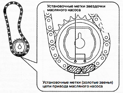
15. Install the drive chain with the oil pump sprocket as one unit, aligning the timing marks on the sprockets and the drive chain as shown in the figure.
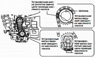
16. Tighten the oil pump sprocket mounting bolt.
17. Install the oil pump drive chain tensioner.
Caution: Do not remove the wire or rolled paper inserted into the tensioner housing at this stage.
18. Install the crankshaft pulley and temporarily screw in the central bolt, then install the special tool shown in the figure to lock the oil pump from turning. Tighten the oil pump sprocket mounting bolt to a torque of 123-140 Nm.
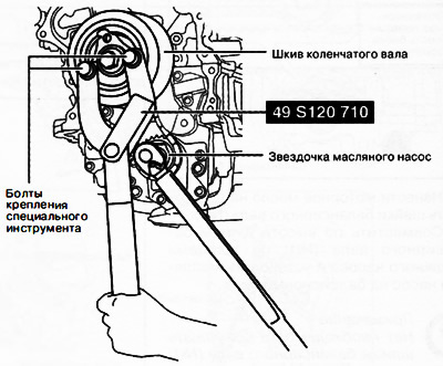
19. Unscrew the temporarily installed central bolt and remove the pulley from the crankshaft. Remove the wire or rolled up paper inserted into the hole in the oil pump housing.
Note: If a new timing chain tensioner is used, remove the installed retainer.
20. Install the remaining parts in the reverse order of removal.
21. Add the required amount of motor oil of the required grade to the engine.
22. Fill with coolant.
23. Check the tightness of the cooling system.
24. Start the engine and check:
- Presence of engine oil leaks.
- Engine oil level.
- Beating and interference of pulleys and drive belt.
- Engine idle speed.