


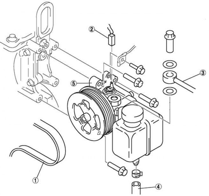
Fig. 5.30. Power steering pump: 1 – drive belt; 2 – pressure sensor connector; 3 – pressure pipeline; 4 – suction hose; 5 – power steering pump
Remove the drive belt.
Disconnect the pressure sensor connector.
Disconnect the pressure line.
Disconnect the suction hose.
Unscrew the three mounting bolts and remove the power steering pump.
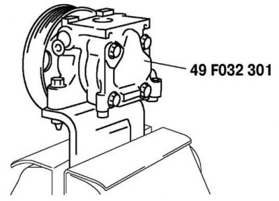
Fig. 5.32. Installing the power steering pump in a vice with soft jaws
Secure the power steering pump using a special device (Fig. 5.32).
Caution: Use a special device to prevent damage to the pump when mounting it in a vice.
Pry up the clip tab using a flat-head screwdriver.

Fig. 5.33. Removing the power steering pump clamp
Remove the clamp using a flat-head screwdriver and a hammer as shown in Figure 5.33.
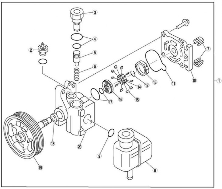
Fig. 5.31. Power steering pump components: 1 – power steering pump; 2 – pressure sensor; 3 – connector; 4 – sealing rings; 5 – control valve; 6 – spring; 7 – clamp; 8 – Power steering expansion tank; 9 – sealing ring; 10 – rear pump housing; 11 – sealing ring; 12 – clamp; 13 – stator ring; 14 – rotor; 15 – blade; 16 – side plate; 17 – sealing ring; 18 – oil seal; 19 – shaft; 20 – front pump housing
Disassemble the remaining components in the order shown in Figure 5.31.