


Disconnect the pressure sensor connector.
Disconnect the pressure line.
Disconnect the suction hose.
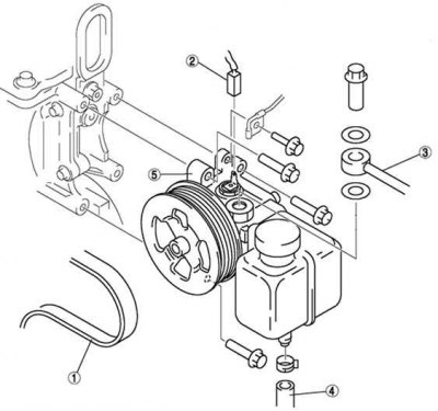
Fig. 5.30. Power steering pump: 1 – drive belt; 2 – pressure sensor connector; 3 – pressure pipeline; 4 – suction hose; 5 – power steering pump
(The original article is available on MazBook)
Unscrew the three mounting bolts and remove the power steering pump.
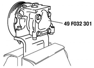
Fig. 5.32. Installing the power steering pump in a vice with soft jaws
Secure the power steering pump using a special device (Fig. 5.32).
Caution: Use a special device to prevent damage to the pump when mounting it in a vice.
Pry up the clip tab using a flat-head screwdriver.
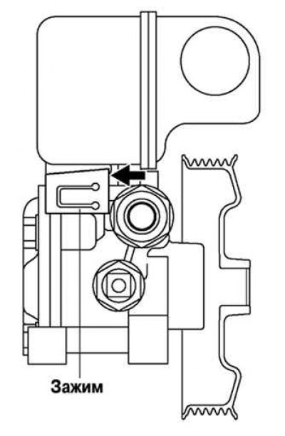
Fig. 5.33. Removing the power steering pump clamp
Remove the clamp using a flat-head screwdriver and a hammer as shown in Figure 5.33.
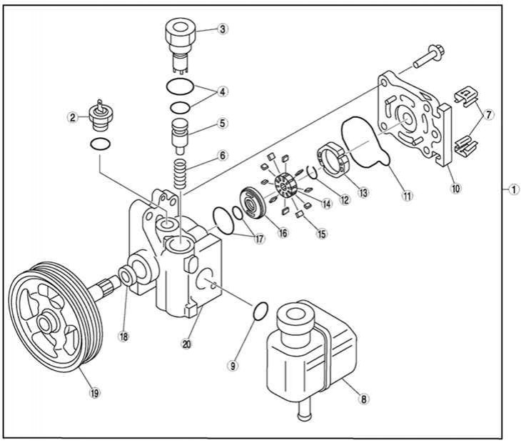
Fig. 5.31. Power steering pump components: 1 – power steering pump; 2 – pressure sensor; 3 – connector; 4 – sealing rings; 5 – control valve; 6 – spring; 7 – clamp; 8 – Power steering expansion tank; 9 – sealing ring; 10 – rear pump housing; 11 – sealing ring; 12 – clamp; 13 – stator ring; 14 – rotor; 15 – blade; 16 – side plate; 17 – sealing ring; 18 – oil seal; 19 – shaft; 20 – front pump housing
Disassemble the remaining components in the order shown in Figure 5.31.