


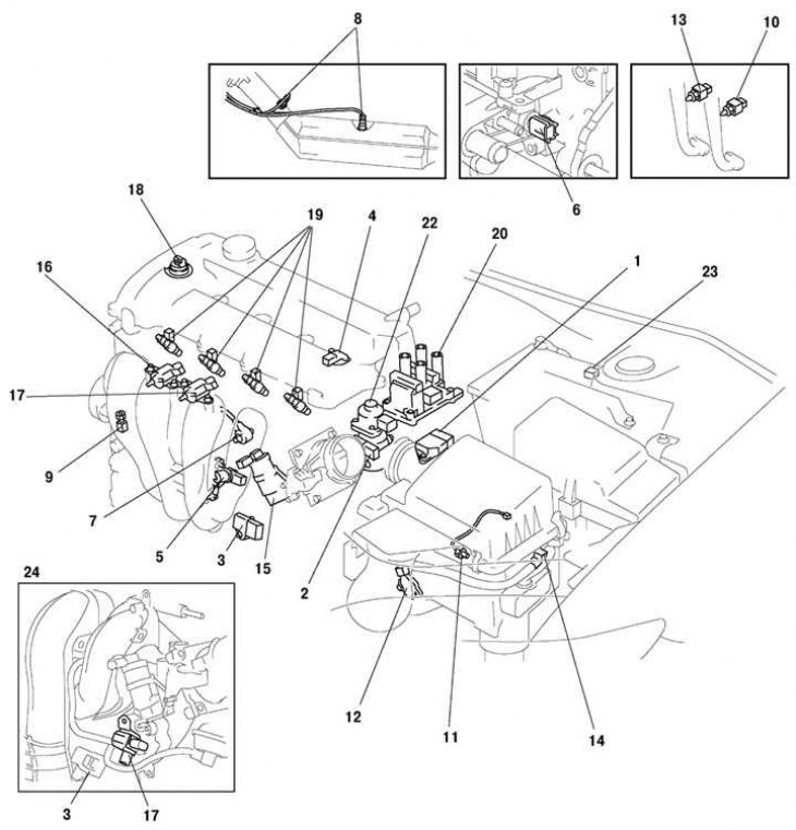
Fig. 2.226. General view of the layout of the components of the Mazda 6 vehicle control system: 1 – Mass air flow/intake air temperature sensor; 2 – throttle position sensor; 3 – absolute pressure sensor in the intake manifold; 4 – camshaft position sensor; 5 – crankshaft position sensor; 6 – coolant temperature sensor; 7 – knock sensor; 8 – heated oxygen concentration sensor (front, back); 9 – Power steering pressure sensor; 10 – clutch switch; 11 – neutral switch; 12 – Gearbox range switch; 13 – Brake light switch; 14 – VAD system control solenoid valve; 15 – idle speed control; 16 – VIC electromagnetic valve; 17 – VTCS electromagnetic valve; 18 – control oil valve; 19 – fuel injector; 20 – ignition coil; 21 – purge valve; 22 – exhaust gas recirculation valve; 23 – pressure sensor; 24 – LF and L8 engines
The general layout of the components of the Mazda 6 vehicle control system is shown in Fig. 2.226.
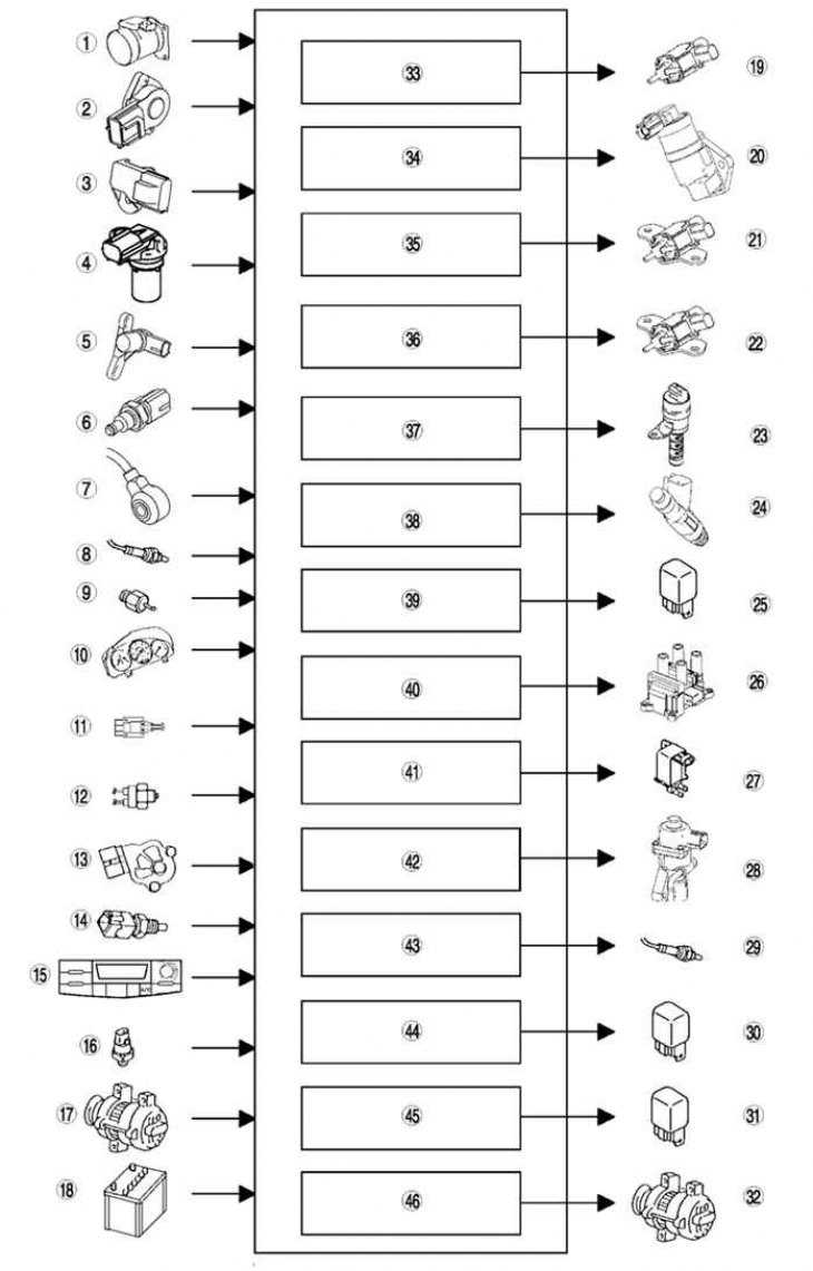
Fig. 2.227. Block diagram of the Mazda 6 vehicle control system: 1 – Mass air flow/intake air temperature sensor; 2 – throttle position sensor; 3 – absolute pressure sensor in the intake manifold; 4 – camshaft position sensor; 5 – crankshaft position sensor; 6 – coolant temperature sensor; 7 – knock sensor; 8 – heated oxygen concentration sensor (front, back); 9 – Power steering pressure sensor; 10 – car speedometer sensor; 11 – Clutch switch; 12 – neutral switch; 13 – Gearbox range switch; 14 – Brake light switch; 15 – Air conditioning system switch; 16 – refrigerant pressure sensor; 17 – generator (pin P: generated voltage); 18 – battery; 19 – VAD system control solenoid valve; 20 – idle speed control; 21 – VIC electromagnetic valve; 22 – VTCS electromagnetic valve; 23 – control oil valve; 24 – fuel injector; 25 – fuel pump relay; 26 – ignition coil; 27 – purge valve; 28 – exhaust gas recirculation valve; 29 – Oxygen concentration sensor heater (front, back); 30 – Air conditioning system relay; 31 – Cooling system fan relay; 32 – generator (terminal D: excitation winding); 33 – VAD system control; 34 – idle speed controller; 35 – VIC; 36 – VTCS; 37 – control of the valve timing mechanism; 38 – fuel injection control; 39 – fuel pump control; 40 – Electronic Spark Advance Control (ESA); 41 – purge control; 42 – exhaust gas recirculation control; 43- oxygen concentration sensor heater control; 44 – Air conditioning system shutdown control; 45 – Electric fan control; 46 – generator control.
Table 2.26. Target engine speed

* Headlights are on, fan switch is set to any speed except 1st, cooling fan is running, and rear window defroster is on.
**The air conditioning switch and fan switch are in the on position.