MazBook.ru
English Русский
Български
Беларускі
Український
Српски
Hrvatski
Română
Polski
Slovenský
Magyar
• Bookmark • Sitemap • Contacts •   
Cars Opel Cars Ford Cars Volkswagen Cars Audi Cars Kia Cars Renault Cars Peugeot


Familia Capella Mazda3 Mazda6 CX-? Others Articles
CX-5KE (2012-2017)

Removal and installation of components of the intake system of a gasoline engine (Mazda CX-5KE)

  • Home
  • Mazda CX-?
  • CX 5 KE (2012-2017)
  • Power unit
  • Intake and exhaust system
  • Removal and installation of components of the intake system of a gasoline engine
0
Contents: Removal ⇓ Installation ⇓
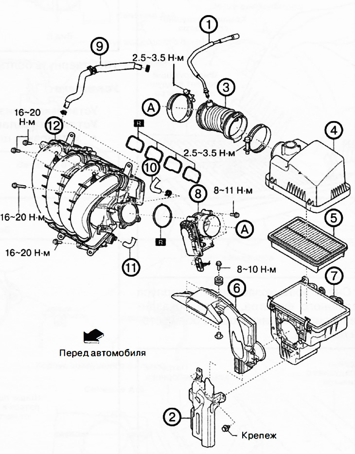
1. Ventilation hose.

1. Ventilation hose.
2. Resonance chamber.
3. Air hose.
4. Air filter cover.
5. Air filter element.
6. Air intake.
7. Air filter housing.
8. Throttle body.
9. Vacuum hose.
10. Fuel vapor hose.
11. Crankcase ventilation hose.
12. Intake manifold.


Note: replace the part with a new one after each removal.


Caution: A hot engine and intake system components can cause various burns. Turn off the engine and wait until it cools before removing intake system components.


Removal


1. Disconnect the negative battery terminal.

2. Disconnect the ventilation hose from the air hose of the intake system.

3. Remove the mass air flow sensor/intake air temperature sensor No.1 (see chapter "Engine management system").


4. Remove the following components as one unit:
  • Air hose
  • Air filter cover
  • Filter element
  • Air filter housing
  • Air intake
  • Resonance chamber

5. Remove the resonance chamber from the air filter housing.

6. Remove the air hose from the air filter housing.

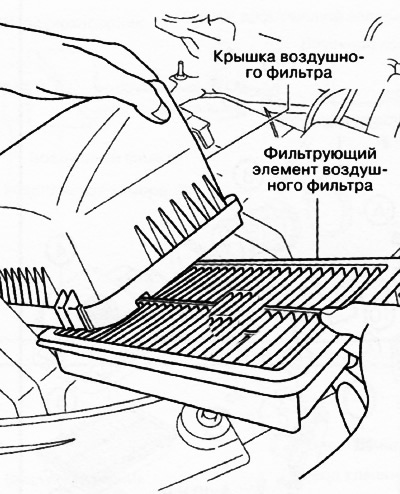
7. Remove the air filter cover and take out the filter element.

7. Remove the air filter cover and take out the filter element.


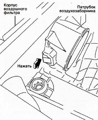
8. Remove the air intake from the air filter housing by pressing the clips shown in the figure on both sides of the pipe.

8. Remove the air intake from the air filter housing by pressing the clips shown in the figure on…


9. Loosen the mounting bolts and remove the throttle body.

10. Remove the decorative engine cover.

11. Remove the vacuum hose.

12. Remove the fuel vapor hose.

13. Remove the forced crankcase ventilation hose.

14. Remove the manifold absolute pressure sensor/intake air temperature sensor No.2 (see chapter "Engine management system").


15. Disconnect the electrical wiring clamp from the intake manifold.
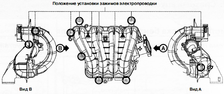
15. Disconnect the electrical wiring clamp from the intake manifold.


16. Loosen the mounting bolts and remove the intake manifold from the engine.

Installation


Installation is carried out in the reverse order of removal, taking into account the following:

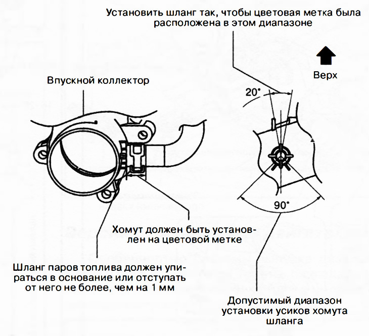
Installing the fuel vapor hose


Install the fuel vapor hose as shown in the figure.

Install the fuel vapor hose as shown in the figure.


Installing a vacuum hose


Install the vacuum hose as shown in the figure.
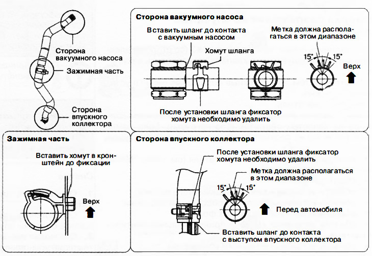
Install the vacuum hose as shown in the figure.


Installing the air filter housing


Install the air filter housing as shown in the figure.
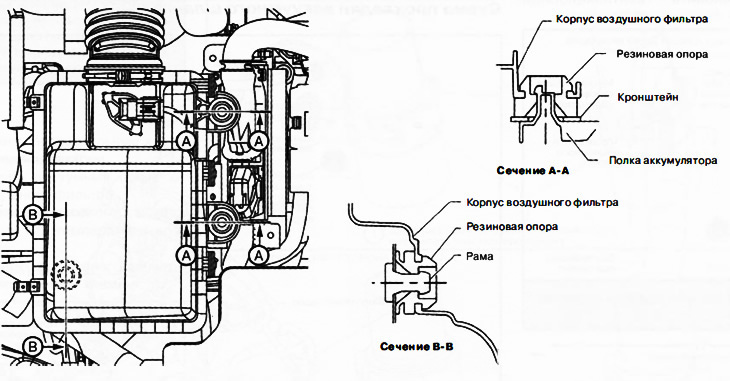


Install the air filter housing as shown in the figure.


Installing the air intake


Install the air intake as shown in the figure.
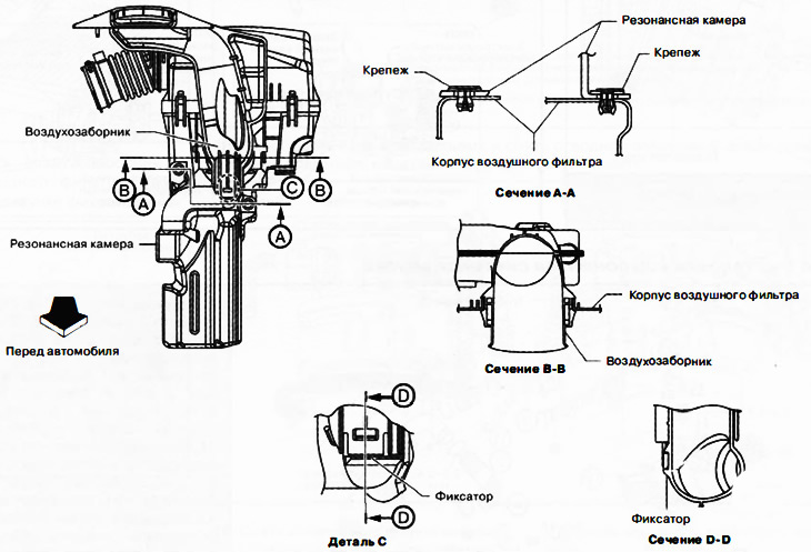
Install the air intake as shown in the figure.


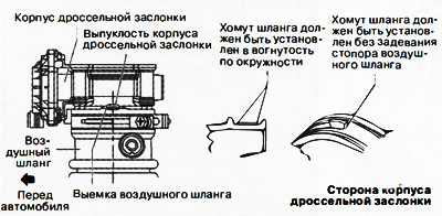
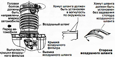
Installing the air hose


Install the air hose as shown in the figures.

Install the air hose as shown in the figures.

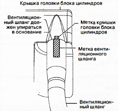
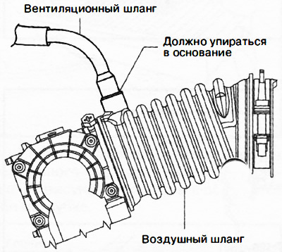
Installing the ventilation hose


Install the ventilation hose as shown in the figures.


Cylinder head cover side

Cylinder head cover side


Air hose side

Air hose side
This article is available at: russian, bulgarian, belarusian, ukrainian, serbian, croatian, romanian, polish, slovak, hungarian
This text was checked by: Evgeny Mereshnikov
Share with friends on social networks:

Previous
CX-5KE » Intake and exhaust system
Next

Checking the vacuum in the intake manifold of a gasoline engine
Vacuum hose routing diagram for the intake system of a gasoline engine
Exhaust system — general description
Intake system — general description
Diesel Engine Intake System Vacuum Hose Routing Diagram
Removal and installation of diesel engine intake system components
Removal and installation of the intercooler of the air intake system…
Checking the intake system components
Checking the exhaust system
More articles on repairing other Mazda models
Fuel injection system of the B6 engine Mazda Familia 5 (1985-1989)
Components of the engine electrical system Mazda Capella 3 (1982-1992, petrol)
Engine Cooling System Components (Diesel) Mazda3 BK (2003-2009)
Engine Management System Components Mazda6 GG (2002-2008)
Engine and exhaust system maintenance Mazda 121 (3) (1996-2003)
Link in different formats to this article
Comments and feedback from visitors
No comments yet


How much will 40 + 33 ?


CX-5KE (2012-2017) 
  • General information
  • Introduction to the guide
  • User manual
  • Maintenance
  • Power unit
  • Petrol engines 2.0 l
  • Petrol engines 2.5 l
  • Diesel engines 2.2 l
  • Cooling system
  • Lubrication system
  • Supply system
  • Control system
  • Intake and exhaust system
  • Engine electrical equipment
  • Transmission
  • Clutch
  • Mechanical gearbox
  • Automatic gearbox
  • Transfer case
  • Drive shafts and cardan
  • Chassis
  • Wheels and tires
  • Front suspension
  • Rear suspension
  • Brake system
  • Steering
  • Body
  • Exterior (external elements)
  • Interior (internal elements)
  • Security systems
  • Heating and air conditioning
  • Electrical equipment
  • Equipment and devices
  • Electrical circuits
MazBook.ru © 2018–2026 · Mobile version · Articles and news · Sitemap: EN BG BY UA RS HR RO PL SK HU · Feedback · Site search · Add to bookmarks Familia 5 (BF) · Familia 6 (BG) · Capella 3 (GC) · Capella 3 and 4 (GC) · Capella 4 (GD) · Capella 5 (GE) · Capella 6 (GF) · Mazda3 BK · Mazda6 GG · CX-5KE · Mazda 121 (3) · Mazda BT-50 (1) ·
By continuing to use the site, you agree to the use of cookies 🔐