


The Controller Area Network (CAN) transmits the following information:
- torque reduction inhibition;
- engine speed;
- vehicle speed;
- throttle position;
- coolant temperature;
- path traveled;
- fuel injection (quantity);
- mIL status;
- generator warning light status;
- engine cylinder displacement;
- number of cylinders;
- intake system type;
- fuel type and supply;
- country;
- gearbox/axle type;
- wheel circumference (front/rear);
- desired gear shift position;
- hOLD switch state.
The Controller Area Network (CAN) receives the following information:
- wheel speed from anti-lock brake system;
- front left;
- front right;
- rear left;
- rear right;
- distance traveled from anti-lock braking system;
- condition of the brake system from the anti-lock braking system;
- anti-lock brake system torque reduction request;
- brake system configuration from anti-lock braking system.
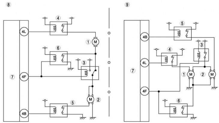
Fig. 2.230. Electrical diagram of the control system of the Mazda 6 with the L8, LF engine (general area) and L3: 1 – electric motor of cooling system fan No.1; 2 – electric motor of cooling system fan No.2; 3 – Cooling system fan relay No.1; 4 – Cooling system fan relay No.2; 5 – Cooling system fan relay No.3; 6 – Cooling system fan relay No.4; 7 – PCM block; 8 – L3 engines; 9 – LF and L8 engines (hot area)
(The text of the article is taken from the website: «MAZBOOK»)
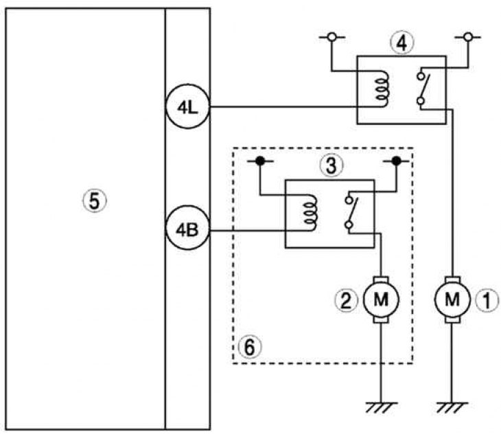
Fig. 2.231. Electrical diagram of the control system of the Mazda 6 with the L8, LF engine (general area): 1 – electric motor of cooling system fan No.1; 2 – electric motor of cooling system fan No.2; 3 – Cooling system fan relay No.1; 4 – Cooling system fan relay No.2; 5 – PCM block; 6 – with air conditioning system