


If the voltage differs from that specified in table 7.8, check the elements and corresponding wire harnesses specified in the "Elements to be checked" column.
Disconnect the instrument panel light control switch connector.
Make sure that the continuity of the circuit at terminal D is as specified in table voltage at the terminals.
If the voltage differs from that specified in table 7.8, check the elements and corresponding wire harnesses specified in the "Elements to be checked" column.
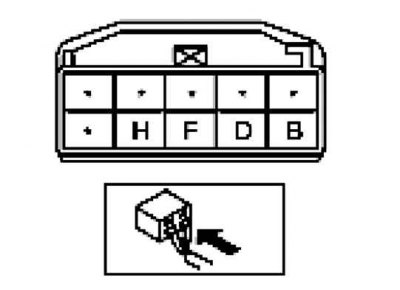
Fig. 7.98. Diagnostic connector of the control switch of lighting on the instrument panel
If the system does not operate properly even though the components or associated wiring harnesses are in good condition, replace the instrument panel light control switch.
Checking the H. conclusions.
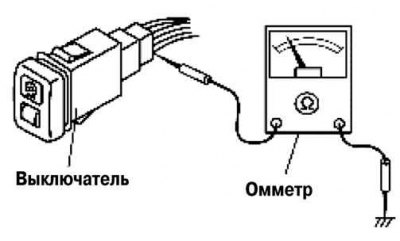
Fig. 7.99. Instrument cluster lighting control switch test diagram
Check the signal waveform at the terminals of the instrument panel lighting control switch H using a tester (Fig. 7.99).
Turn the light switch to the TNS or ON position.
Make sure that the resistance changes smoothly when turning the instrument panel light control switch from the highest brightness position to the lowest brightness position.