


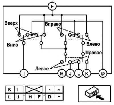
Fig. 7.94. Diagnostic connector of the electric exterior mirror switch
If the check results are not normal, replace the power outside mirror switch.
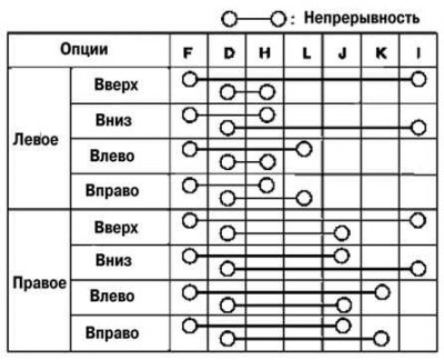
Fig. 7.95. Circuit continuity test diagram between the terminals of the outside mirror switch
[The original text can be found on mazbook.ru]