


Front part
Disconnect the negative cable from the battery.
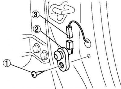
Fig. 7.45. Procedure for removing door limit switch components: 1 – screw; 2 – door switch; 3 – connector
Remove in the order shown in Figure 7.45.
Install in the reverse order of removal.
Rear end
Disconnect the negative cable from the battery.
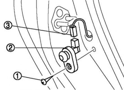
Fig. 7.46. Procedure for removing door limit switch components: 1 – screw; 2 – door switch; 3 – connector
Remove in the order shown in Figure 7.46.
Install in the reverse order of removal.
Checking the door limit switch
Remove the door limit switch.
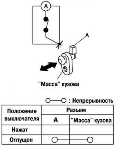
Fig. 7.47. Door limit switch test diagram
Check the integrity of the circuit between the door switch terminal and the base of the housing using an ohmmeter (Fig. 7.47).
If the measurements do not correspond to the data given in table, replace the limit switch.