


Removing
Remove the battery cover.
Disconnect the negative cable from the battery.
Remove the bottom cover.
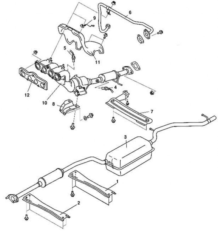
Pic. 2.331. Components of the exhaust system of a car with a Z6 engine: 1 - cross member of the rear tunnel; 2 - cross member of the front tunnel; 3 - main muffler; 4 - rear oxygen concentration sensor with heating; 5 - front oxygen concentration sensor with heating; 6 - exhaust gas recirculation pipe (from the exhaust manifold); 7 - element; 8 - exhaust manifold bracket; 9 - clamp; 10 - three-way catalytic converter; 11 - thermal screen of the exhaust manifold; 12 - exhaust manifold gasket
Remove components in the order shown in figure 2.331.
Removing the exhaust manifold / exhaust manifold heat shield
Attention! Excessive bending of the exhaust pipe may damage it.
Note. When removing the exhaust manifold, slightly move the exhaust manifold heat shield aside, loosen the nuts, and then remove the exhaust manifold with the shield. Refer to the following procedure.
Remove the front wheels.
Remove the air filter cover and air filter housing.
Remove the EGR pipe (from the intake manifold).
Remove the EGR valve assembly.
Disconnect the steering shaft from the steering mechanism, disconnect the steering rods.
Disconnect the pressure hose and return hose.
Remove the #1 engine mount.
Loosen the exhaust manifold heat shield bolts.
Move the exhaust manifold heat shield a little to the side and loosen the exhaust manifold nuts.
Remove the bolts securing the front cross member and front stabilizer bar.
Loosen the front cross member mounting bolts and lower the front cross member about 100mm.
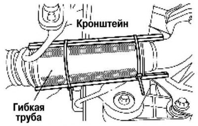
Pic. 2.332. Fastening flexible pipe
Tie up a flexible pipe or fix it, as shown in Figure 2.332.
Remove the exhaust manifold along with the insulator by lowering it to the bottom of the car.
Installation
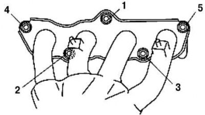
Pic. 2.333. The order of tightening the bolts of the exhaust manifold
Tighten nuts of fastening of a final collector in the order shown in drawing 2.333.
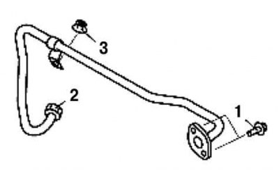
Pic. 2.334. The order of tightening the bolts and nuts of the exhaust gas recirculation pipe
Tighten the bolts and nuts of the exhaust gas recirculation pipe in the order shown in Figure 2.334.
Install other components in the reverse order of removal