
Removal and installation of components of system of release
Attention.
- A hot engine and exhaust system components can cause various burns. Shut off the engine and wait until it cools down before removing the exhaust system components.
- Remove / install the exhaust gas temperature sensor only if it is necessary to check or replace, for example, when codes appear, this is faulty. Each removal of the exhaust gas temperature sensor can lead to a leak in the exhaust pipe, therefore, after reinstalling the sensor, it is necessary to verify that there are no exhaust gas leaks.
Note:
- If the diesel particulate filter indicator illuminates on the instrument panel, the diesel particulate filter adjustment and manual regeneration procedure must be performed before removing the exhaust system components.
- If the particulate filter indicator on the instrument panel begins to flash, check for a malfunction in the particulate filter system.
- If the catalytic converter is replaced with a new one, the particulate filter initialization procedure must be performed.
1. Disconnect the negative battery terminal.
2. Remove the components of the exhaust system in the sequence shown in the figures.
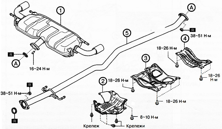
Front wheel drive versions (2WD):
1. Main muffler.
2. Plate.
3. Staple.
4. Tunnel cross member.
5. The middle part of the exhaust pipe.
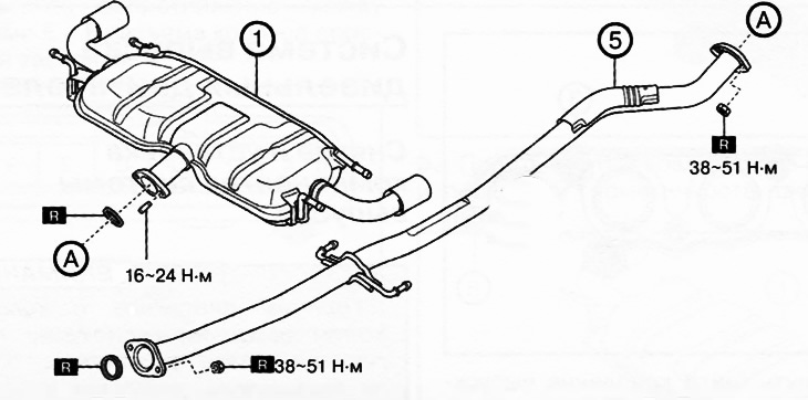
Versions with all-wheel drive (4WD):
1. Main muffler.
2. The middle part of the exhaust pipe.
Note:replace the part with a new one after each removal.
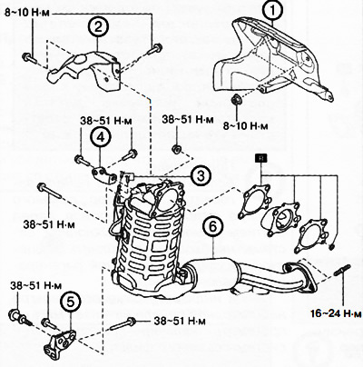
1. Insulator.
2. Catalytic converter insulator.
3. Exhaust hose
4. Upper catalytic converter bracket.
5. Lower catalytic converter bracket.
6. Catalytic converter.
Note:replace the part with a new one after each removal.
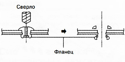
Note: The rear exhaust insulator is mounted on rivets that need to be drilled to remove the insulator with a 5mm drill bit.
Note: When removing the catalytic converter, disconnect the No. 1 and No. 2 exhaust gas temperature sensor connectors, as well as the air fuel ratio sensor connector.
3. To install the catalytic converter, do the following:
Fit the bolt and nuts shown in the illustration.
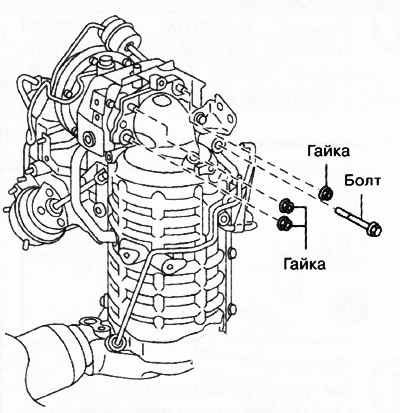
Tighten the bolt and nuts in the sequence shown in the figure to a torque of 38-51 Nm.
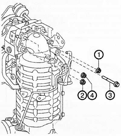
Screw on bolts 1 and bolt 2 as shown in the illustration.
Tighten bolts 1 to 38-51 Nm.
Tighten bolt 2 to 38-51 Nm.
Screw on bolts 3 and bolt 4 as shown in the figure.
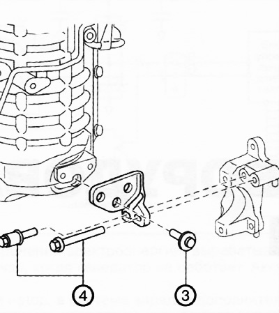
Tighten bolts 3 and 4 to 38-51 Nm.
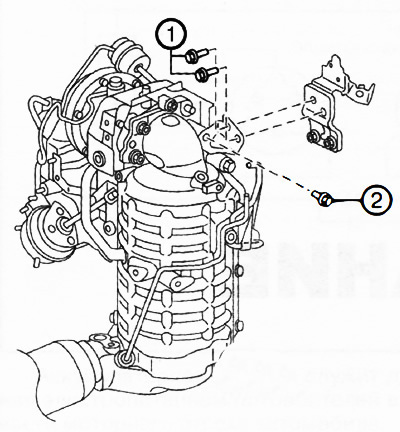
Fit screws 5 and 6 as shown in the figure.
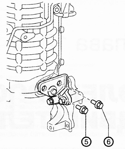
Tighten bolts 5 and 6 to 38-51 Nm.
After installation, check once again that the tightening torques of all fasteners are correct.
7. Further installation is carried out in the reverse order of removal.