


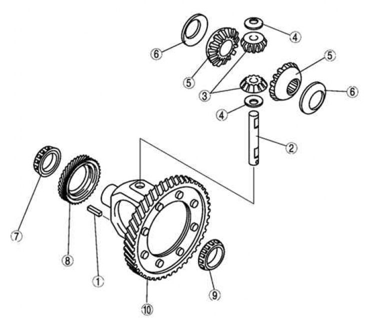
Fig. 3.50. Differential assembly components: 1 – gear ring and housing; 2 – bearing (from the side of the toothed ring); 3 – speedometer drive pinion; 4 – bearing (from the side opposite the toothed rim); 5 – thrust washer; 6 – axle gear; 7 – thrust washer; 8 – satellite; 9 – satellite axis; 10 – cylindrical pin
Note: Perform assembly in the order shown in Figure 3.50. Installation of individual differential components, as well as testing procedures, are given below in this section.
[Text taken from an online platform: MAZBOOK.RU]