
Attention! Perform disassembly in the order shown in Figure 3.35. Procedures for removing individual crankcase components are provided later in this section.
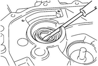
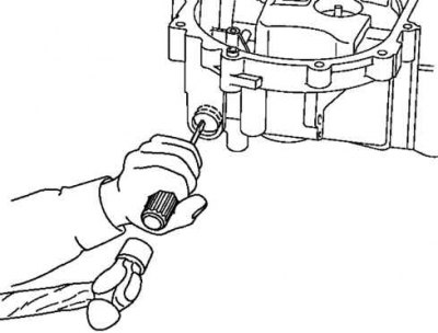
Pic. 3.36. Removing the input shaft seal
Remove the input shaft seal using a screwdriver (pic. 3.36).
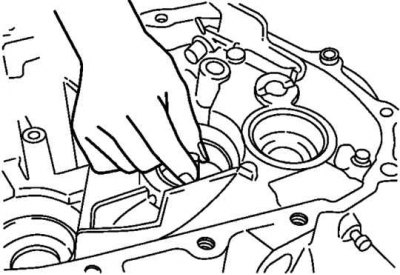
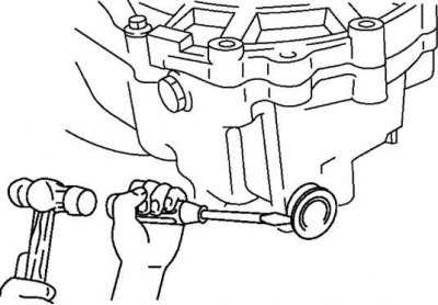
Pic. 3.37. Removing the output shaft bearing
Remove the output shaft bearing race and bell together (pic. 3.37).
To disassemble the roll pin, align the clutch housing pin removal slot with the roll pin position.
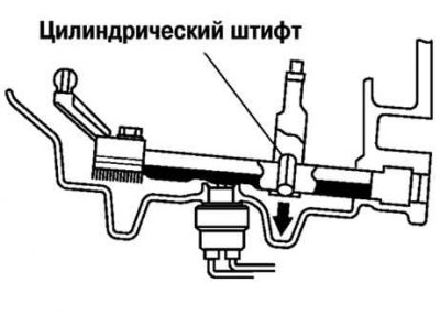
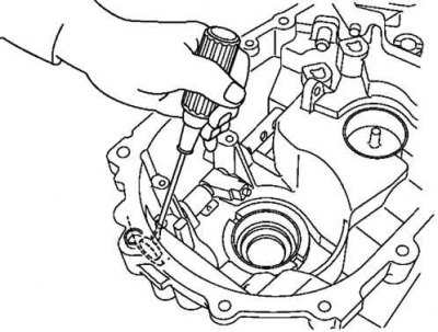
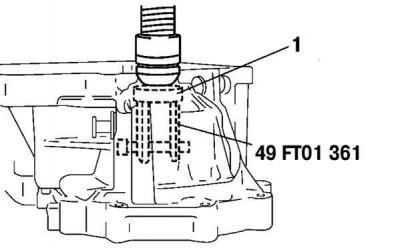
Pic. 3.38. Roll pin disassembly diagram
Knock out the pin using a beard with a thin sting (pic. 3.38).
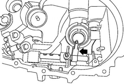
Pic. 3.39. Movement of the control rod before removal
To remove the control rod, move it in the direction of the arrow shown in Figure 3.39.
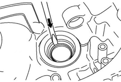
Pic. 3.40. Punching a hole in the crankcase cover
Using a flat head screwdriver and a hammer, poke a hole in the cover (pic. 3.40).
Pic. 3.41. Removing the sealing cap
Remove the sealing cap by inserting a flathead screwdriver into the hole on the inside of the crankcase (pic. 3.41).
Pic. 3.42. Removing the control rod gland
Remove the control rod seal using a screwdriver (pic. 3.42).
Pic. 3.43. Removing the differential seal
Remove the differential seal using a screwdriver (pic. 3.43).
Pic. 3.44. Removing the outer ring of the differential bearing: 1 - bearing race
Before disassembling the differential bearing race, remove the outer race of the bearing using a special tool (pic. 3.44).
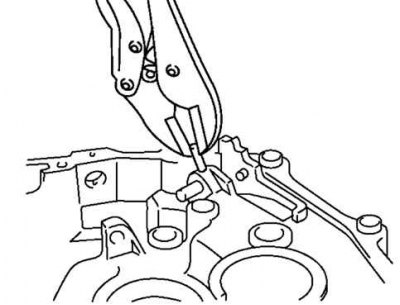
Pic. 3.45. Removing roll pin
To remove the reverse lever shaft, first use pliers to remove the roll pin (pic. 3.45).
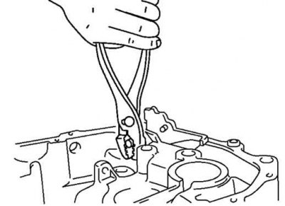
Pic. 3.46. Removing the reverse lever shaft
Protect the reverse lever shaft with a rag and using the same pliers, remove the shaft (pic. 3.46).
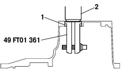
Pic. 3.47. Removing the main gear housing bearing race: 1 - bearing race; 2 - press
Using the special tool, remove the main gear housing bearing race (pic. 3.47)