


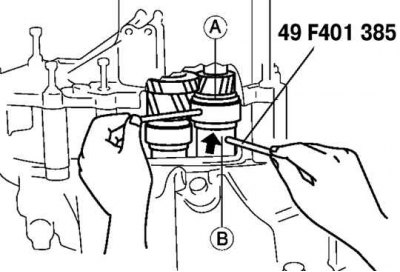
Fig. 3.59. Eliminating gaps before installing bearings
To install the bearings, install special devices (rods) in the holes A and B of the selectors and turn the selectors in such a way as to increase the clearance. Then turn the special device in the opposite direction until the clearances are eliminated (Fig. 3.59).
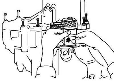
Fig. 3.60. Manually expanding selectors
Manually expand the selectors to the stop (Fig. 3.60).
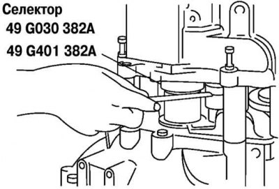
Fig. 3.61. Measuring the gap in the selector
Use a feeler gauge to measure the gap in the special device (selector) (Fig. 3.61).
Caution! Measure the gap around the entire circumference of the selector.
Caution: Remember the maximum value and select the gasket as follows.
Input Shaft Shim: Select the thinnest acceptable shim from the chart to obtain standard clearance.
Standard gap: 0–0.05 mm.
Example:
- probe measurement value - 0.57 mm;
- range of gasket thicknesses: (0.57 mm - 0.05 mm) - (0.57 mm - 0 mm)= 0.52 mm - 0.57 mm;
- gasket: 0.55 mm.
Secondary Shaft Shim: Select the thinnest acceptable secondary shaft shim from the chart to obtain standard clearance.
Preload value: 0.03–0.08 mm.
Example:
- probe measurement value: 0.57 mm;
- range of gasket thicknesses: (0.57 mm + 0.03 mm) - (0.57 mm + 0.08 mm) = 0.60 mm - 0.65 mm;
- gasket: 0.60 mm.
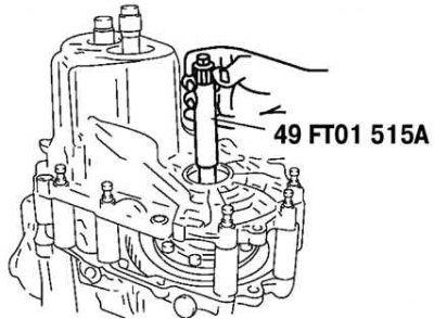
Fig. 3.62. Installing a torque wrench
Install a special device and a dynamometer or torque wrench (Fig. 3.62).
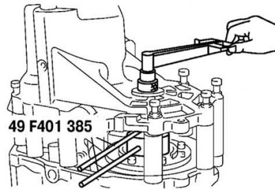
Fig. 3.63. Adjusting the selector clearance
Adjust the clearance of the special device (selector) to obtain a certain preload/dynamometer value (Fig. 3.63).
Note: Read the preload value when the differential begins to turn.
Note: Measure several times and calculate the average.
- - Preload: 0.5 Nm.
- - Value on the dynamometer: 5 N.
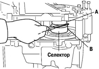
Fig. 3.64. Measuring the clearance in the selector for the differential
Use a feeler gauge to measure the clearance in the differential selector (Fig. 3.64).
Add 0.15mm to the measured gap and select the shim combination that gives the closest value to the measured one.
Example:
- 0.32 mm + 0.15 mm = 0.47 mm.
- The nearest gasket (on the thick side): 0.47 mm - 0.50 mm
Remove the final drive housing and special tool.
Remove the selectors, input shaft and differential.
Remove the bearing races.
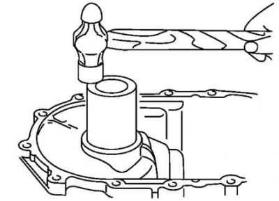
Fig. 3.65. Installing the primary shaft bearing race
Install the adjusting shim(s) and the input shaft bearing race using a suitable pipe (Fig. 3.65).
Caution: Use the adjusting shim(s) selected when adjusting the bearing preload.
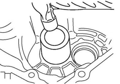
Fig. 3.66. Installing the differential shaft bearing cage
Install the adjusting shim(s) and differential shaft bearing race using a suitable pipe (Fig. 3.66).
Caution: Use the adjusting shim(s) selected when adjusting the bearing preload.