


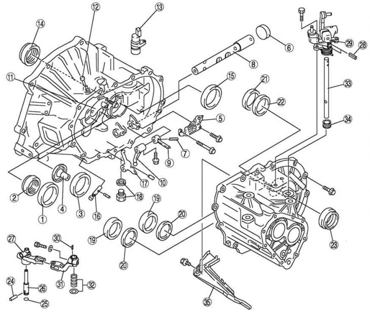
Fig. 3.35. Clutch housing disassembly components: 1 – bearing cage (primary shaft); 2 – oil seal (primary shaft); 3 – bearing cage (secondary shaft); 4 – socket; 5 – guide plate element; 6 – lip seal; 7 – cylindrical pin; 8 – control rod; 9 – selector; 10 – change lever; 11 – breather cover element; 12 – breather; 13 – plug; 14 – oil seal (differential); 15 – bearing cage (differential); 16 – reverse gear lever shaft; 17 – reverse gear lever; 18 – drain plug and washer; 19 – bearing cage (main gear housing); 20 – adjusting gasket; 21 – bearing cage (differential); 22 – adjusting gasket; 23 – oil seal (differential); 24 – mounting pin; 25 – sealing ring; 26 – crankshaft; 27 – elements of the crank lever; 28 – cylindrical pin; 29 – gear shift lever element; 30 – key; 31 – end of control; 32 - spring and washer; 33 – gear shift lever shaft; 34 – covers; 35 – oil channel
Note: Perform disassembly in the order shown in Figure 3.35. The procedures for removing individual crankcase components are given later in this section.
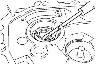
Fig. 3.36. Removing the primary shaft seal
Remove the primary shaft seal using a screwdriver (Fig. 3.36).
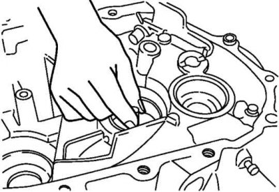
Fig. 3.37. Removing the secondary shaft bearing
Remove the secondary shaft bearing race and socket together (Fig. 3.37).
To disassemble the roll pin, align the clutch housing pin removal slot with the position of the roll pin.
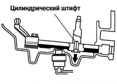
Fig. 3.38. Scheme of disassembling a cylindrical pin
Knock out the pin using a fine-point punch (Fig. 3.38).
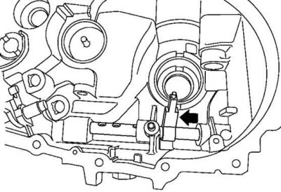
Fig. 3.39. Moving the control rod before removal
To remove the control rod, move it in the direction of the arrow shown in Figure 3.39.
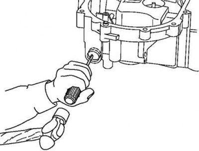
Fig. 3.40. Punching a hole in the crankcase cover
Using a flat-head screwdriver and a hammer, make a hole in the cover (Fig. 3.40).
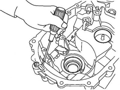
Fig. 3.41. Removing the sealing cap
Remove the sealing cap by inserting a flat-head screwdriver into the hole on the inside of the crankcase (Fig. 3.41).
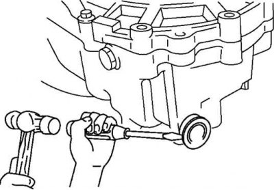
Fig. 3.42. Removing the control rod seal
Remove the control rod seal using a screwdriver (Fig. 3.42).
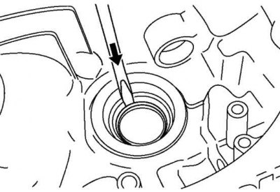
Fig. 3.43. Removing the differential seal
Remove the differential seal using a screwdriver (Fig. 3.43).
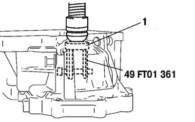
Fig. 3.44. Removing the outer ring of the differential bearing: 1 – bearing cage
Before disassembling the differential bearing race, remove the outer bearing ring using a special tool (Fig. 3.44).
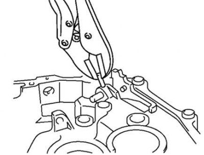
Fig. 3.45. Removing the cylindrical pin
To remove the reverse gear lever shaft, first remove the cylindrical pin using pliers (Fig. 3.45).

Fig. 3.46. Removing the reverse gear lever shaft
Protect the reverse gear lever shaft with a rag and, using the same pliers, remove the shaft (Fig. 3.46).
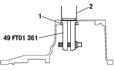
Fig. 3.47. Removing the main gear housing bearing race: 1 – bearing cage; 2 – press
(The original article is posted on: «mazbook.ru»)
Using a special tool, remove the main gear housing bearing race (Fig. 3.47).