


The sealed cooling system includes a belt-driven water pump, radiator fan, radiator, expansion tank, thermostat and heater core, hoses and switches. When a cold engine is started, coolant circulates around the cylinder block and cylinder head. Warm coolant passes through the heater core to the water pump. As the coolant expands when heated, its level in the expansion tank rises. The flow of coolant through the radiator is stopped by closing the thermostat. When the coolant reaches a certain temperature, the thermostat opens and the hot coolant passes through the hose to the radiator. As the coolant passes through the radiator, it is cooled by the oncoming air flow.
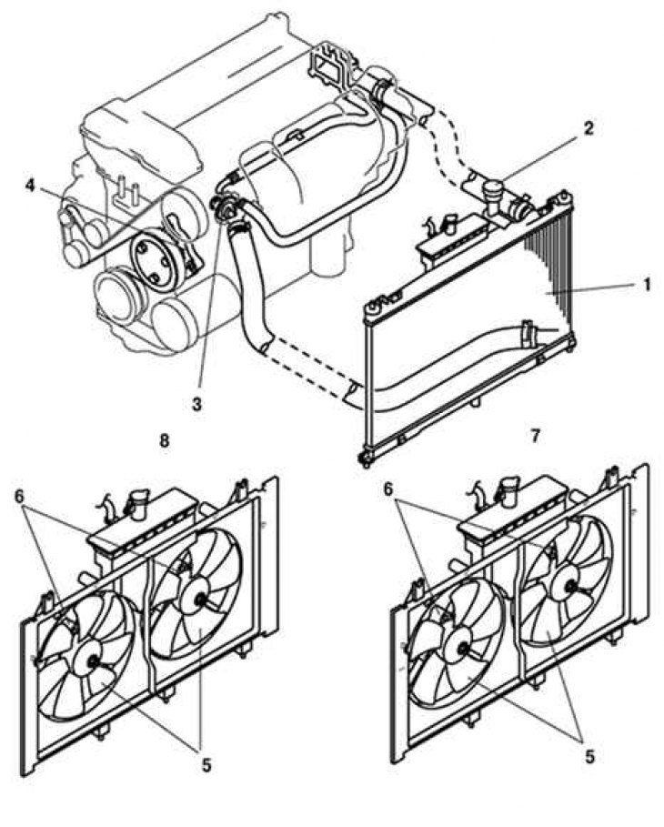
Fig. 2.47. Components of the cooling system of Mazda 6 cars: 1 – radiator; 2 – radiator cap; 3 – thermostat; 4 – coolant pump; 5 – cooling system fan blade; 6 – cooling system fan motor No.1, cooling system fan motor No.2; 7 – L3 engines; 8 – LF engines, excluding engines for L8
The thermostat housing is located near the radiator on four-cylinder engines and at the top rear of the engine on six-cylinder engines (Fig. 2.47).
Table 2.17. Cooling system specifications
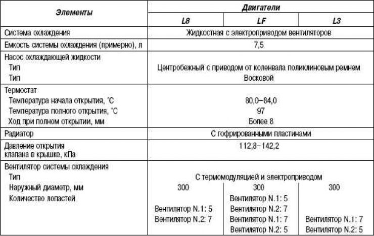
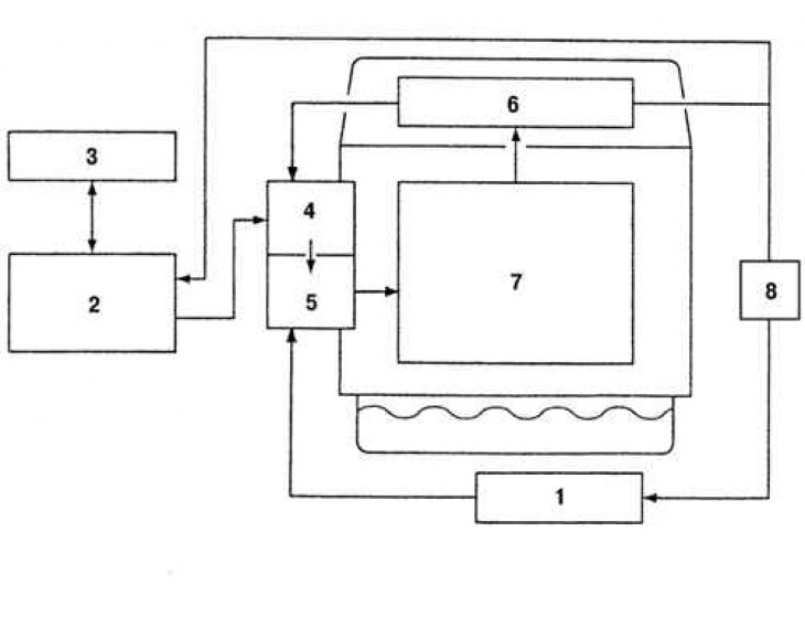
Fig. 2.48. Block diagram of the cooling system of LF and L3 engine models: 1 – heater; 2 – radiator; 3 – refrigerant expansion tank; 4 – thermostat; 5 – coolant pump; 6 – cylinder head; 7 – cylinder block; 8 – oil cooler
(Based on website data: MAZBOOK)