


Contents: Rules for handling electrical…⇓ Cable colors ⇓ Plug symbols ⇓ Mass connections ⇓ Abbreviations in diagrams ⇓
Rules for handling electrical circuits
If you need to find a fault in the electrical system or install additional electrical equipment, you cannot do without a diagram showing the current flow and cable connections. The corresponding current circuit must be closed, otherwise the current will not flow. For example, it is not enough when voltage is applied to the positive terminal of the headlight, but the circuit on the ground contact is not closed.
Therefore, the battery ground cable is connected to the body. However, this ground connection is not sufficient, and the corresponding consumer has a ground wire directly, whose insulation is usually black. Switches, relays, fuses, measuring devices, electric motors or other electrical elements can be built into the individual current circuits. In order to be able to connect these devices correctly, the individual cables have different colors.
Cable colors
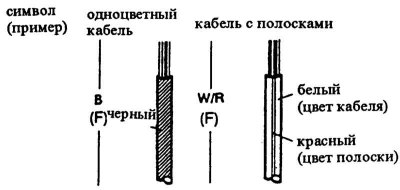
The letters on the individual conductors indicate the color of the cable:
- 1 - symbol (example)
- 2 - single color cable
- 3 - black
- 4 - cable with stripes
- 5 - white (cable color)
- 6 - red (stripe color)
Single letters indicate a single-color cable.
Example: B - black. For two-color cables, the first letter indicates the main color of the cable, the second letter indicates the color of the stripe.
Example: W/R means a white cable with a red stripe. The letter in brackets next to it denotes the corresponding cable harness.
Example: (F) - Front wiring harness in the instrument panel and in the right engine compartment.
Cable color codes
| Code | Color |
| L | blue |
| B | black |
| BR | brown |
| DL | dark blue |
| DG | dark green |
| G | green |
| GY | grey |
| LB | light gray |
| LG | light green |
| N | beige |
| O | orange |
| P | pink |
| R | red |
| PU | purple |
| T | beige |
| W | white |
| Y | yellow |
| V | violet |
Article is based on website data: www.mazbook.ru
Plug symbols
The plugs and sockets are designated on the diagram as follows:

Identical plugs are connected in the diagram with a dashed line. A plug without a color designation is colorless or white. Sockets that are not used are marked with an asterisk (*).
Mass connections
The ground connections in the diagram are usually at the bottom.

If the ground connection is made by a cable, the ground point is indicated by a number. If the ground connection is made directly through the body, this is indicated on the diagram by a filled dot.
Abbreviations in diagrams
| A | amperes |
| ABS | anti-lock braking system |
| ACC | additional equipment |
| A/C | air conditioner |
| A/T | automatic transmission |
| ALT | generator |
| B | battery |
| B/L | upper/leg compartment |
| CPU | electronic control device |
| CCT | switching circuit |
| COMBI | combi |
| DEF | defroster |
| DIESEL | diesel cars |
| ECU | engine control device |
| EGI | electronic injection system |
| EGR | exhaust gas recirculation |
| ELEC | electric |
| F | in front |
| FL | front left |
| FR | front right |
| F/B | control |
| F/I | injection valve |
| GEN | generator |
| H/D | heater/defroster |
| HEAT | heater |
| HI | high beam |
| IG | ignition |
| ILLUMI | lighting |
| INT | interval drive |
| J/B | fuse box |
| LH | left |
| LO | low beam |
| M/T | manual transmission |
| NC | normally closed (closeer) |
| NO | normally open (circuit breaker) |
| OFF | turned off |
| ON | included |
| P/S | servo control |
| R | behind |
| RH | on the right |
| RL | back left |
| RPM | rpm = revolutions per minute |
| RR | back right |
| SQ | square millimeters |
| SW | switch |
| TEMP | temperature |
| V | volts |
| VOL | volumes |
| W | watts |