


Design and operating principle
The power window motor is equipped with a connector and a gear.
Two proximity switches on the Hall sensor are mounted in the connector.
The Hall Effect sensor proximity switch uses a set of magnets on a rotating shaft to sense the rotation of the power window motor and outputs a synchronized pulse to the main window switch.
The contactless switch on the Hall sensor No.1 produces one pulse for each revolution of the window lifter motor axis. Accordingly, the main window lifter switch determines the angular speed of rotation of the motor.
The main switch determines the direction of rotation of the window lift motor based on the difference between the highest and lowest points of the pulse from each contactless switch on Hall sensors No.1 and 2.
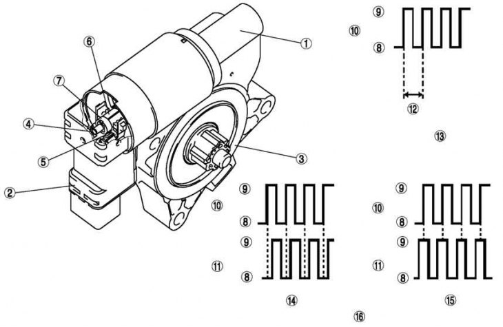
Fig. 8.31. Electric window lift motor with servo drive: 1 – electric motor; 2 – connector; 3 – gear; 4 – contactless switch on Hall sensor No.1; 5 – contactless switch on Hall sensor No.2; 6 – shaft; 7 – magnet; 8 - low; 9 - high; 10 – pulse (contactless switch on Hall sensor No.1); 11 – pulse (contactless switch on Hall sensor No.2); 12 – one revolution of the electric window lift motor with servo drive; 13 – glass movement distance detection; 14 – up; 15 – down; 16 – detection of glass movement direction