


Contents: Checking the gap between the wheel…⇓ Resistance check ⇓ Checking voltage ⇓ Checking the signal shape ⇓
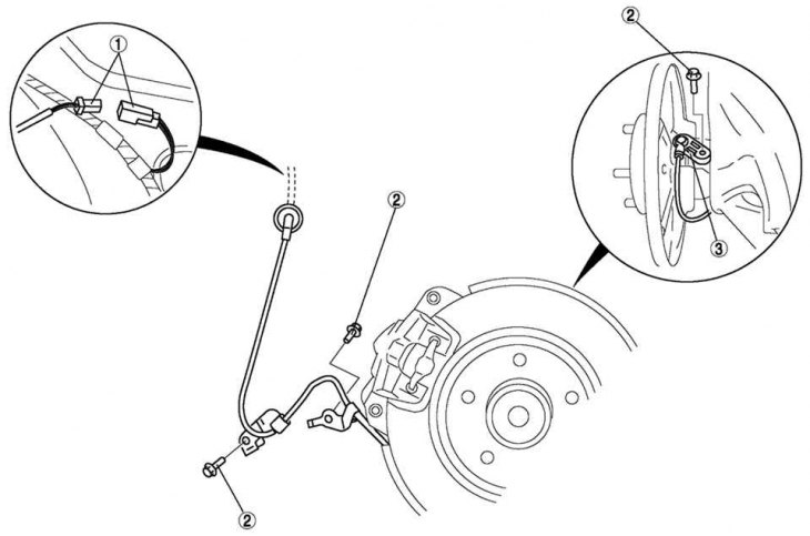
Fig. 6.49. Rear ABS wheel speed sensor: 1 – connector; 2 – mounting bracket bolts; 3 – sensor
The installation location of the rear ABS wheel speed sensor is shown in Fig. 6.49.
Checking the gap between the wheel speed sensor and the sensor rotor
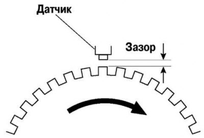
Fig. 6.50. Checking the gap between the wheel speed sensor and the sensor rotor
Check the gap between the wheel speed sensor and the sensor rotor (Fig. 6.50).
(The original article is on: Mazbook.ru)
Gap: 0.3–1.1 mm.
Resistance check
Disconnect the ABS wheel speed sensor connector.
Remove the mounting bracket bolts and disconnect the ABS sensor.
Check the resistance of the anti-lock brake system wheel speed sensor.
If the resistance is not within the normal range, replace the ABS wheel speed sensor.
Resistance: 1.3–1.7 kOhm.
Checking voltage
Place the vehicle on a horizontal surface, lift it with a jack and lower it onto supports.
Disconnect the ABS wheel speed sensor connector.
Test each sensor while rotating each wheel at one revolution per second.
If the values are not within the normal range, replace the ABS wheel speed sensor.
Voltage: 0.25-1.20V (aC).
Checking the signal shape
Place the vehicle on a horizontal surface, lift it with a jack and lower it onto supports.
Disconnect the ABS wheel speed sensor connector.
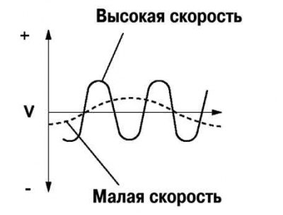
Fig. 6.51. Waveform verification diagram
Using an oscilloscope, check the voltage waveform for distortion and noise as each wheel rotates (Figure 6.51).
If there is distortion or noise, check the ABS sensor rotor.