


Contents: Disassembly ⇓ Assembly ⇓
Caution! If the master cylinder housing is damaged, replace the master cylinder assembly. When securing the master cylinder in a vice, clamp only the master cylinder lug (Fig. 6.28).
Disassembly
Remove the cap and strainer from the master cylinder reservoir.
Unscrew the fastening screw and remove the tank.
Remove the two sealing rings.
Place the cylinder in a vice.
Using a screwdriver, push the pistons out to their full stroke, loosen the lock bolt and remove the O-ring.
Based on website data [Mazbook]
Note: Wrap the screwdriver with a bandage or adhesive tape to avoid damaging the pistons and cylinder bore.
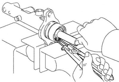
Fig. 6.29. Removing the spring ring
Press the piston with a screwdriver and use circlip pliers to remove the circlip (Fig. 6.29).
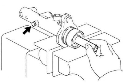
Fig. 6.30. Removing the primary piston with spring
Unscrew the piston lock bolt with the gasket and remove the primary piston with the spring, pulling it out strictly along the axis without distortion (Fig. 6.30).
Note: If the piston is removed at an angle, the cylinder bore may be damaged.
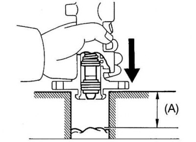
Fig. 6.31. Removing the secondary piston
Place a rag on two wooden blocks and lightly tap the cylinder flange against the blocks until the secondary piston comes out. Make sure that the distance (A) shown in Figure 6.31 from the rag to the top of the blocks is at least 100 mm.
Make sure there is no rust or scratches on the cylinder mirror.
Check the cylinder for wear or damage.
Replace the cylinder if necessary.
Caution: Replace all parts in the repair kit used to service the brake master cylinder.
Caution! When installing, lubricate the rubber parts with clean brake fluid to facilitate assembly. Do not use industrial compressed air to dry and clean the brake mechanism parts. This may damage the rubber parts. If any part of the hydraulic system is removed or disconnected, bleed the brake system completely.
Caution: Perform all repair work on a clean workbench.
Assembly
Install the secondary and primary pistons.
Install a new O-ring onto the lock screw.
Fully retract the primary piston assembly.
Install and tighten the lock screw.
Tightening torque: 2.0–2.4 Nm.
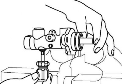
Fig. 6.32. First check of the secondary piston assembly
Press and release the secondary piston assembly, making sure it is held in place by the locking screw (Fig. 6.32).
Install the secondary piston so that the hole faces the lock pin and primary piston.
Install a new O-ring onto the retaining pin.
Fully retract the primary piston assembly.
Install and tighten the locking pin.
Tightening torque: 6.9–9.8 Nm.
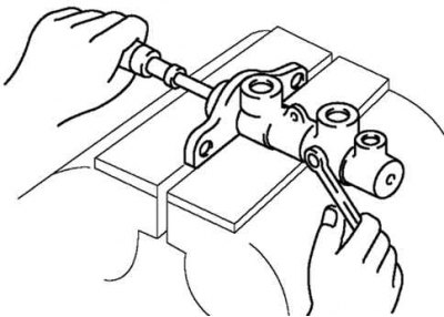
Fig. 6.33. Secondary piston assembly check
Press and release the secondary piston assembly, making sure it is held in place by the locking screw (Fig. 6.33).