


Contents: Removal ⇓ Installation ⇓
Removal
For models with automatic transmission - remove the locking mechanism with the brake light switch (right hand drive models only).
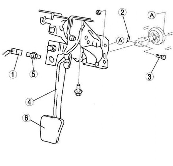
Fig. 6.19. Procedure for removing brake pedal parts: 1 – Brake light switch connector; 2 – spring pin; 3 – pin with a head and a hole for a cotter pin; 4 – brake pedal; 5 – brake light switch; 6 – pedal support platform
Remove in the order shown in Figure 6.19.
Installation
Install in the reverse order of removal, taking into account the following.
Secure the brake light switch to the bracket with a force of 50 N.
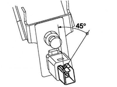
Fig. 6.20. Turning the brake light switch 45°
Turn the brake light switch 45° counterclockwise (Fig. 6.20).
Check that the brake light switch is securely locked.
Note: It is not necessary to adjust the clearance of the limiter bolt and pedal limiter after the brake light switch is securely locked.