
MazBook.ru
English Русский
Български
Беларускі
Український
Српски
Hrvatski
Română
Polski
Slovenský
Magyar
• Bookmark • Sitemap • Contacts •   
Cars Opel Cars Ford Cars Volkswagen Cars Audi Cars Kia Cars Renault Cars Peugeot


Familia Capella Mazda3 Mazda6 CX-? Others Articles
Mazda6 GG (2002-2008)

Removal and installation the master brake cylinder (Mazda 6 GG)

  • Home
  • Mazda 6
  • Mazda6 GG (2002-2008)
  • Chassis
  • Brake system
  • Removal and installation the master brake cylinder
0
Contents: Removal ⇓ Installation ⇓

Removal


Caution! Do not allow brake fluid to come into contact with painted surfaces. If brake fluid does come into contact with a painted surface, wash it off immediately.


Drain the brake fluid.

Disconnect the brake fluid level sensor connector.

Disconnect the brake line, disconnect the brake pipes from the master cylinder.

Unscrew the two mounting nuts, remove the nipple, the master brake cylinder and the gasket.
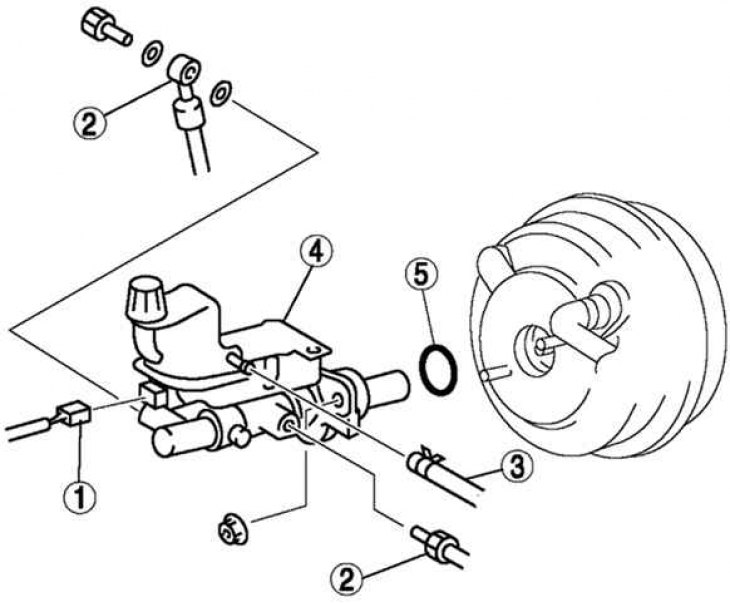
Fig. 6.21. Dismantling components of the master brake cylinder: 1 – brake fluid level sensor…

Fig. 6.21. Dismantling components of the master brake cylinder: 1 – brake fluid level sensor connector; 2 – brake line; 3 – hose (models with manual transmission); 4 – master cylinder; 5 – sealing ring


Installation


Caution: Always install the brake booster tappet shim before performing any verification measurements or adjustments.
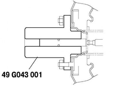

Fig. 6.22. Installing a special device on the brake booster

Fig. 6.22. Installing a special device on the brake booster


Install the special tool to the brake booster as shown in Figure 6.22 and tighten to the specified torque.

Tightening torque: 9.8–16.0 Nm.
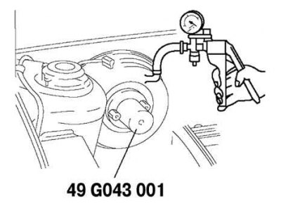
Fig. 6.23. Creating a vacuum in the brake booster

Fig. 6.23. Creating a vacuum in the brake booster


Using a vacuum gauge, create a vacuum in the brake booster equal to 66.7 kPa (Fig. 6.23).
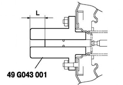
Fig. 6.24. Measuring the length of the pusher

Fig. 6.24. Measuring the length of the pusher


Using a caliper, measure the distance L as shown in Figure 6.24.

Standard length: 22.7mm.
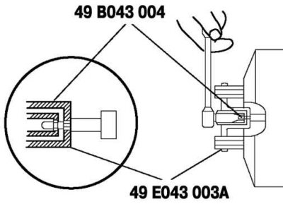
Fig. 6.25. Adjusting the pusher length

Fig. 6.25. Adjusting the pusher length


If the L dimension is not as shown, remove the special tool (49 E043 001) and a special device (49 B043 004) adjust the length of the pusher. Use the special tool (E043 003A) to prevent the pusher from rotating (Fig. 6.25).

Remove special tools, replace special tool (49 E043 001) and measure the distance L again.
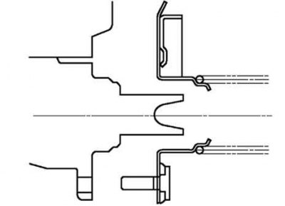
Fig. 6.26. Diagram of correct installation of the master cylinder on the brake booster

Fig. 6.26. Diagram of correct installation of the master cylinder on the brake booster


Install the master cylinder onto the brake booster (Fig. 6.26).

Caution! If after installing the master cylinder, air does not properly escape from the brake system pipes even after the procedure for removing it, there may be incomplete release of the wheels or another defect. Remove the master cylinder and reinstall it properly.
This article is available at: russian, bulgarian, belarusian, ukrainian, serbian, croatian, romanian, polish, slovak, hungarian
This text was checked by: Evdokia Filimonova
Share with friends on social networks:

Previous
Mazda6 GG » Brake system
Next

Removal and installation the brake pedal
Checking the brake light switch
Checking the pedal-to-floor clearance
Adjusting the brake pedal clearance
Checking the brake pedal clearance
Checking the liquid level sensor
Disassembly and assembly of the master cylinder
Removal and installation the front brake disc
Checking the brake disc and brake components
Replacing the front brake pads
More articles on repairing other Mazda models
Brake master cylinder and vacuum booster Mazda Familia 5 (1985-1989)
Drum brake master cylinder — removal, overhaul and installation Mazda Capella 3 (1982-1992, petrol)
Master Brake Cylinder — Description Mazda3 BK (2003-2009)
Master brake cylinder Mazda CX-5KE (2012-2017)
Removal and installation the master brake cylinder Mazda BT-50 (1) (2006-2011)
Link in different formats to this article
Comments and feedback from visitors
No comments yet


How much will 31 + 18 ?


Mazda6 GG (2002-2008) 
  • User manual
  • Vehicle description
  • Keys, locks and alarms
  • Controls and instruments
  • Air conditioning and heater
  • Seat adjustment
  • Security systems
  • Driving and operation
  • Faults en route
  • Maintenance
  • Power unit
  • Engine device
  • Engine repair
  • Lubrication system
  • Cooling system
  • Fuel system
  • Exhaust system
  • Electrical equipment of engines
  • Control system
  • Transmission
  • Clutch
  • Mechanical gearbox
  • Automatic gearbox
  • Drive shafts and hubs
  • Chassis
  • Suspension and wheels
  • Steering
  • Brake system
  • Body
  • Exterior (external elements)
  • Interior (internal elements)
  • Doors and windows
  • Air conditioning and heater
  • Electrical equipment
  • Equipment and devices
  • Power devices
  • Lighting system
  • Windshield wipers and washers
MazBook.ru © 2018–2026 · Mobile version · Articles and news · Sitemap: EN BG BY UA RS HR RO PL SK HU · Feedback · Site search · Add to bookmarks Familia 5 (BF) · Familia 6 (BG) · Capella 3 (GC) · Capella 3 and 4 (GC) · Capella 4 (GD) · Capella 5 (GE) · Capella 6 (GF) · Mazda3 BK · Mazda6 GG · CX-5KE · Mazda 121 (3) · Mazda BT-50 (1) ·
By continuing to use the site, you agree to the use of cookies 🔐