


Removal the wheel stub with the hub
Caution: Performing the following procedure without first removing the front ABS wheel sensor may cause an accidental open circuit in the wiring harness. Disconnect the front ABS wheel sensor wiring harness before performing the following procedures (from the drive shaft side) and secure the wiring in a suitable location where it will not be accidentally touched when servicing the vehicle.
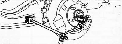
1. When working on the left side of the vehicle, disconnect the automatic leveling sensor linkage.
2. All-wheel drive (4WD) versions:
Loosen the drive shaft lock nut.
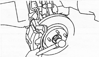
Install the spare nut onto the drive shaft threads so that the edge of the nut is flush with the end of the drive shaft.
- Tap the nut with a brass hammer to knock the drive shaft out of the front wheel hub.
- Disconnect the drive shaft from the wheel hub.
3. Remove the ABS wheel sensor.
4. Remove the brake hose clamp.
5. Remove the brake caliper assembly (see chapter "Brake system") and put it aside, hanging it on the body with wire.
6. Remove the brake disc (see chapter "Brake system").
7. Loosen the bolts securing the wheel hub to the journal and remove the wheel hub with the dust cover.
8. Loosen the lower nut of the anti-roll bar strut and disconnect the strut from the lower suspension arm.
9. Support the lower arm of the rear suspension with a jack.
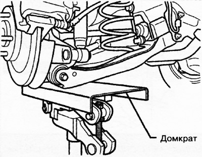
10. Loosen the outer bolt of the lower arm of the rear suspension.
11. Remove the rear suspension coil spring (see chapter "Suspension").
12. Unscrew the lower bolt of the rear shock absorber.
13. Loosen the outer bolt of the rear suspension cross rod.
14. Loosen the rear suspension trailing arm mounting bolt.
15. Loosen the outer bolt of the upper arm of the rear suspension and remove the trunnion.
16. If necessary, use a press to remove the bolts from the wheel hub.
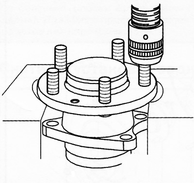
Note: Wheel hub bolts should only be removed for replacement.
17. If necessary, remove the bushings from the journal:
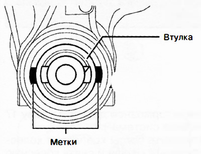
Apply marks to the journal as shown in the figure.
Using a special tool, press the bushing out of the journal.
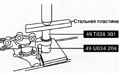
Pressing out the front axle bushing
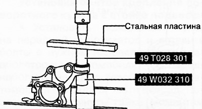
Pressing out the rear bushing from the journal
Installing a wheel stub with a hub
Installation is carried out in the reverse order of removal, taking into account the following:
Installing bushings into the journal
Align the projections on the journal bushing with the marks made during removal.
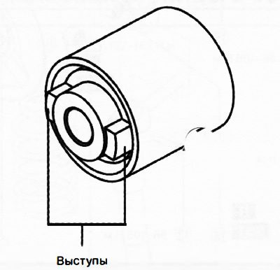
Install the new bushing into the journal using a press.
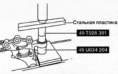
Pressing in the front axle bushing
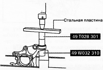
Pressing in the rear hub bushing
Installing wheel hub bolts
Use a press to install new wheel hub bolts.
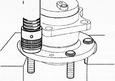
Installing wheel hub mounting bolts
Attention: Wheel hub mounting bolts are tightened to a certain angle, but do not reach the yield point (as is the case with cylinder head bolts). Therefore, there is no need to check the length of the bolts.
Tightening the drive shaft lock nut (4WD versions)
After tightening the lock nut to a torque of 390 Nm, unscrew it by 180 degrees, then tighten it again to a torque of 236-274 Nm.
Note: After installation, check and, if necessary, adjust the wheel alignment angles.