


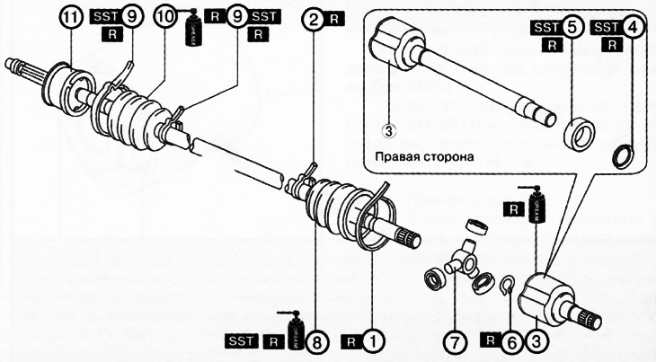
1. Large diameter boot clamp (from the gearbox side).
2. Small diameter boot clamp (from the gearbox side).
3. Outer ring.
4. Dust ring (if equipped).
5. Bearing.
6. Retaining ring.
7. Tripod.
8. Dust cover on the gearbox side.
9. Dust cover clamp (from the wheel side).
10. Dust cover on the wheel side.
11. Shaft with ball CV joint.
Note:
: replace the part with a new one after each removal.
: use a special tool or device.
: apply lubricant.
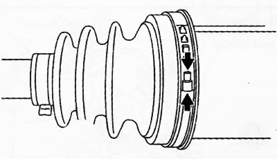
1. Using pliers, pry up the boot clamp at the points shown in the figure and remove the large diameter clamp from the boot on the gearbox side.
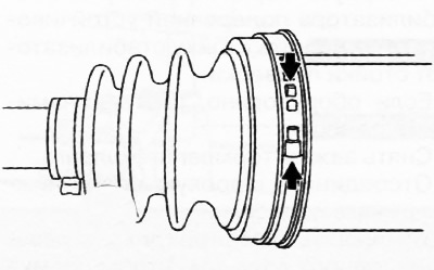
Note: The small diameter boot clamp is removed only if it is damaged.
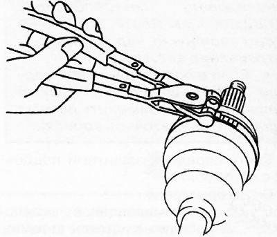
2. Remove the small diameter boot clamp using special pliers.
3. Mark the position of the outer ring relative to the shaft for correct assembly later.
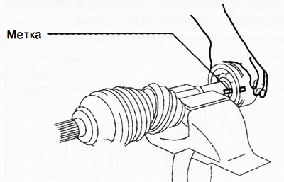
4. Fix the drive shaft in a vice.
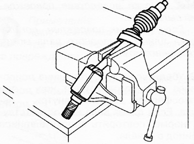
5. Lightly tap the outer ring with a hammer through a wooden or plastic block, then remove the outer ring from the drive shaft.
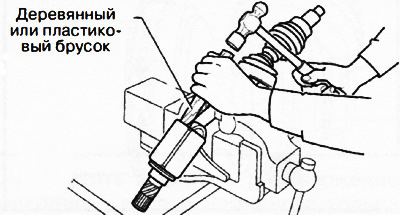
Caution: Be careful when striking the outer ring, otherwise there is a risk of damage to the tripod joint rollers.
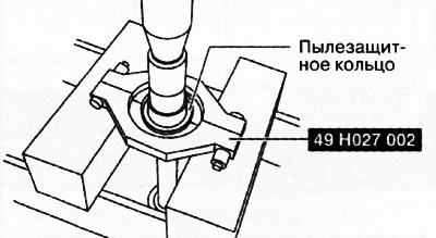
6. If equipped, remove the dust ring using a press and a special tool.
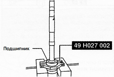
7. Remove the bearing from the drive shaft using a press and a special tool.
8. Apply alignment marks to the shaft and Tripod joint.
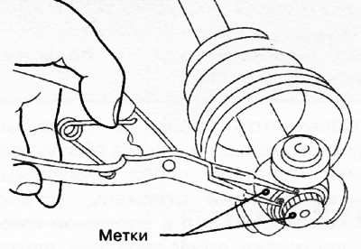
9. Using special pliers, remove the retaining ring.
10. Remove the Tripod joint from the shaft.
Caution: Do not attempt to knock the Tripod joint off the shaft with a hammer. This may damage the Tripod joint.
Note: Remove the wheel side boot only if faulty.
11. Wrap the shaft splines with electrical tape.
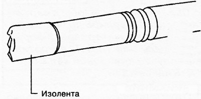
12. Remove the clamps and remove the boot from the wheel side of the shaft.
Note: The drive shaft boots on the wheel side and the gearbox side are different. Be careful not to mix up the boots when installing.
13. Place grease inside the new boot on the wheel side.
Note:
Do not touch the grease with your hands. Apply grease with a grease gun to prevent foreign materials from entering the dust boot.
Amount of grease:
- Petrol engine SKYACT/VG 2.0: 96-106 g.
- Diesel engine SKYACT/VD 2.2: 160-180 g.
14. After making sure that the shaft splines are still covered with electrical tape, install the boot onto the drive shaft.
15. Remove the electrical tape from the shaft splines.
16. Adjust the gap A to 2.9 mm by turning the adjusting screw of the special crimping tool.
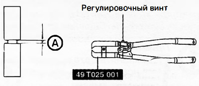
17. Tighten the small clamp of the boot on the wheel side using a special tool. Make sure that the gap B is within the norm (2.4-2.8 mm). If the gap B exceeds the permissible range, reduce the gap A on the crimping tool and crimp the clamp again. If the gap B is less than the norm, replace the boot clamp with a new one, increase the gap A on the crimping tool and crimp the new clamp.
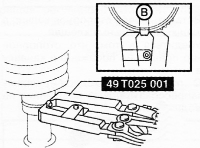
18. Make sure that the boot clamp does not protrude beyond the boot mounting areas. If the clamp is not installed where it should be, replace the boot clamp with a new one, repeating the operations described above.
19. Adjust the gap C to 3.2 mm by turning the adjusting screw of the special crimping tool.
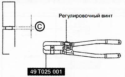
20. Tighten the large clamp of the boot on the wheel side using a special tool. Make sure that the clearance D is within the norm (2.4-2.8 mm). If the gap D exceeds the permissible range, reduce the gap C on the crimping tool and crimp the clamp again. If the gap D is less than the norm, replace the boot clamp with a new one, increase the gap C on the crimping tool and crimp the new clamp.
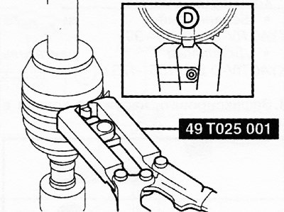
21. Make sure that the boot clamp does not protrude beyond the boot mounting areas. If the clamp is not installed where it should be, replace the boot clamp with a new one, repeating the operations described above.
22. Having aligned the installation marks on the shaft and the joint, install the Tripod joint on the shaft using a hammer and a suitable rod.
[The article is based on website data: MAZBOOK.ru]
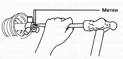
23. Insert a new retaining ring using special pliers.
24. Make sure that the retaining ring is correctly seated in the shaft groove.
25. Using a suitable mandrel, press the new bearing onto the drive shaft.
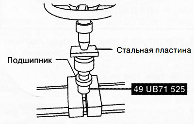
26. Using a suitable mandrel, press the new dust ring onto the drive shaft.
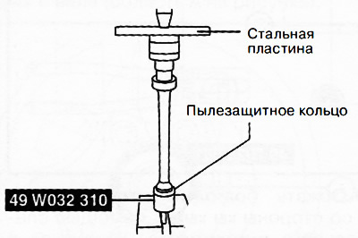
27. Place in outer ring with dust cover (from the gearbox side) necessary lubrication.
Note:
Do not touch the grease with your hands. Apply grease with a grease gun to prevent foreign materials from entering the boot. Grease quantity:
- SKYACTIV-G 2.0 petrol engine: 89-99 g.
- Diesel engine SKYACTIV-0 2.2: 155-175 g.
28. Fix the outer ring in a vice.
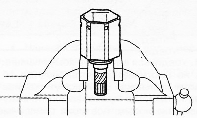
Caution: Use caution when clamping the outer ring in a vice, as this may deform the outer ring seal.
29. Align the rollers with the grooves of the outer ring and, lightly tapping the rollers with a hammer through a wooden or plastic rod, install the drive shaft into the outer ring, holding the drive shaft vertically.
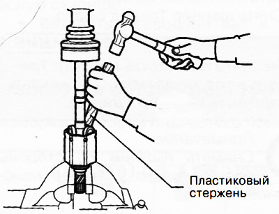
Caution: Make sure that no foreign material gets into the outer ring of the joint (for example, dust or dirt), otherwise the drive shaft may be damaged.
30. Adjust the length of the drive shaft to the standard value (see section "Service data" at the beginning of the chapter).
31. Bleed all the air out of the boots by carefully lifting the small diameter edges of each boot with a flat screwdriver wrapped in cloth.
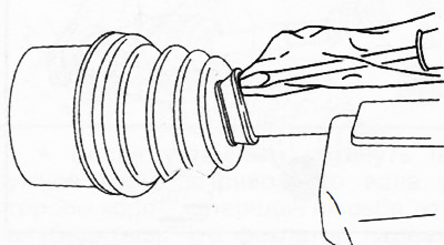
Note:
- Make sure there are no grease leaks due to damage to the anthers.
- If the boot is damaged, it may become impossible to adjust the drive shaft length.
32. Make sure that the drive shaft length is within the standard at atmospheric pressure inside the boot. If the shaft length is not within the standard, repeat the Tripod joint assembly from the beginning.
33. Using pliers, pry up the large diameter boot clamp at the points shown in the figure and tighten the clamp.
34. Make sure the clamp is securely installed on the boot.