
MazBook.ru
English Русский
Български
Беларускі
Український
Српски
Hrvatski
Română
Polski
Slovenský
Magyar
• Bookmark • Sitemap • Contacts •   
Cars Opel Cars Ford Cars Volkswagen Cars Audi Cars Kia Cars Renault Cars Peugeot


Familia Capella Mazda3 Mazda6 CX-? Others Articles
CX-5KE (2012-2017)

Removal and installation the wheel hub and steering knuckle (Mazda CX-5KE)

  • Home
  • Mazda CX-?
  • CX 5 KE (2012-2017)
  • Transmission
  • Drive shafts and cardan
  • Removal and installation the wheel hub and steering knuckle
0
Contents: Removal the steering knuckle with…⇓ Installing the steering knuckle with…⇓
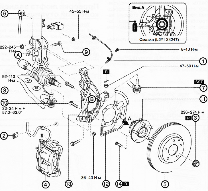
1. ABS wheel sensor.

1. ABS wheel sensor.
2. Brake hose clamp.
3. Lock nut.
4. Brake caliper assembly.
5. Brake disc.
6. Upper part of the anti-roll bar.
7. Ball joint of the steering rod end.
8. Ball joint of the lower arm of the front suspension.
9. Front shock absorber bolts.
10. Wheel hub mounting bolts.
11. Wheel hub.
12. Dust cover.
13. Steering knuckle.
14. Wheel hub bolts.


Note:

: replace the part with a new one after each removal.

: use a special tool or device.

: apply lubricant.


Removal the steering knuckle with the wheel hub


Caution: Performing the following procedure without first removing the front ABS wheel sensor may cause an accidental open circuit in the wiring harness. Disconnect the front ABS wheel sensor wiring harness before performing the following procedures (from the drive shaft side) and secure the wiring in a suitable location where it will not be accidentally touched when servicing the vehicle.


1. Loosen the mounting bolt and remove the front ABS wheel sensor.

2. Remove the brake hose clamp.

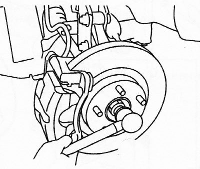
3. Loosen the drive shaft lock nut.
3. Loosen the drive shaft lock nut.


4. Install the spare nut onto the drive shaft threads so that the edge of the nut is flush with the end of the drive shaft.

5. Tap the nut with a brass hammer to knock the drive shaft out of the front wheel hub.

6. Disconnect the drive shaft from the wheel hub.

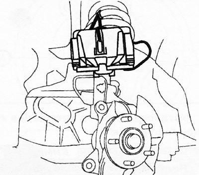
7. Remove the brake caliper assembly (see chapter "Brake system") and put it aside, hanging it on the car body with a wire.
7. Remove the brake caliper assembly (see chapter «Brake system») and put it aside, hanging it on…


8. Remove the brake disc (see chapter "Brake system").


9. Loosen the nut and disconnect the upper part of the anti-roll bar from the suspension strut.

10. Disconnect the steering rod end from the steering knuckle.

11. Disconnect the lower ball joint from the steering knuckle.

12. Loosen the bolts securing the front shock absorber to the steering knuckle and remove the steering knuckle assembly.

13. Loosen the bolts securing the wheel hub to the steering knuckle.

14. Remove the wheel hub and dust cover from the steering knuckle.

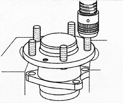
15. If necessary, use a press to remove the bolts from the wheel hub.
15. If necessary, use a press to remove the bolts from the wheel hub.


Note: Wheel hub bolts should only be removed for replacement.


Installing the steering knuckle with the wheel hub


Installation is carried out in the reverse order of removal, taking into account the following:

Installing wheel hub bolts


Use a press to install new wheel hub bolts.
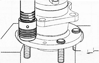
Use a press to install new wheel hub bolts.


Installing a wheel hub


Apply lubricant (L2Y1 33247) on the inner ring of the wheel bearing and the contact surface of the drive shaft (area A in the figure).
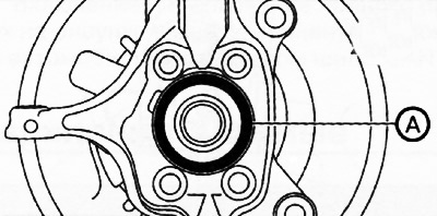


Apply lubricant (L2Y1 33247) on the inner ring of the wheel bearing and the contact surface of the…


Installing wheel hub mounting bolts


Attention: Wheel hub mounting bolts are tightened to a certain angle, but do not reach the yield point (as is the case with cylinder head bolts). Therefore, there is no need to check the length of the bolts.


Installing the bolts securing the steering knuckle to the suspension strut


Install the steering knuckle on the front shock absorber and insert the bolts in the desired direction: on the right side of the car - from the front to the back, on the left side of the car - from the rear to the front. Then tighten the nuts to a torque of 222-245 Nm.

Tightening the drive shaft lock nut


After tightening the lock nut to a torque of 390 Nm, unscrew it by 180 degrees, then tighten it again to a torque of 236-274 Nm.

Note: After installation, check the wheel alignment angles and adjust if necessary.
This article is available at: russian, bulgarian, belarusian, ukrainian, serbian, croatian, romanian, polish, slovak, hungarian
This text was checked by: Evgeny Mereshnikov
Share with friends on social networks:

Previous
CX-5KE » Drive shafts and cardan
Next

Front axle of the car — checking from the wheel hub with the steering…
General procedures
Service data
All-wheel drive control system
Rear final drive
Removal and installation the rear wheel hub assembly
Checking the play of the rear wheel hub
Checking the front drive shaft
Removal and installation the front drive shaft
Disassembly and assembly of the front drive shaft with a tripod joint
More articles on repairing other Mazda models
Steering / Front Wheel Drive Mazda Familia 6 (1989-1994)
Key left in steering wheel lock reminder signal Mazda Capella 3 (1982-1992, petrol)
Steering wheel adjustment Mazda3 BK (2003-2009)
Steering wheel adjustment Mazda6 GG (2002-2008)
Front wheel hub and steering knuckle — device Mazda BT-50 (1) (2006-2011)
Link in different formats to this article
Comments and feedback from visitors
No comments yet


How much will 16 + 23 ?


CX-5KE (2012-2017) 
  • General information
  • Introduction to the guide
  • User manual
  • Maintenance
  • Power unit
  • Petrol engines 2.0 l
  • Petrol engines 2.5 l
  • Diesel engines 2.2 l
  • Cooling system
  • Lubrication system
  • Supply system
  • Control system
  • Intake and exhaust system
  • Engine electrical equipment
  • Transmission
  • Clutch
  • Mechanical gearbox
  • Automatic gearbox
  • Transfer case
  • Drive shafts and cardan
  • Chassis
  • Wheels and tires
  • Front suspension
  • Rear suspension
  • Brake system
  • Steering
  • Body
  • Exterior (external elements)
  • Interior (internal elements)
  • Security systems
  • Heating and air conditioning
  • Electrical equipment
  • Equipment and devices
  • Electrical circuits
MazBook.ru © 2018–2026 · Mobile version · Articles and news · Sitemap: EN BG BY UA RS HR RO PL SK HU · Feedback · Site search · Add to bookmarks Familia 5 (BF) · Familia 6 (BG) · Capella 3 (GC) · Capella 3 and 4 (GC) · Capella 4 (GD) · Capella 5 (GE) · Capella 6 (GF) · Mazda3 BK · Mazda6 GG · CX-5KE · Mazda 121 (3) · Mazda BT-50 (1) ·
By continuing to use the site, you agree to the use of cookies 🔐