


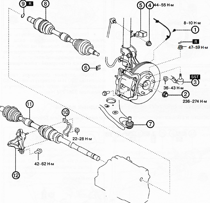
1. ABS wheel sensor.
2. Drive shaft lock nut.
3. Ball joint of the steering rod end.
4. Upper nut of the anti-roll bar.
5. Dynamic damper (if equipped).
6. Brake hose clamp.
7. Ball joint of the lower suspension arm.
8. Left drive shaft.
9. Drive shaft lock.
10. Bracket No.2.
11. Right drive shaft.
12. Bracket No.1.
Note:
: replace the part with a new one after each removal.
: use a special tool or device.
Attention.
- Performing the following procedure without first removing the front ABS wheel sensor may cause an accidental open circuit in the wiring. Disconnect the front ABS wheel sensor wiring before performing the following procedures (from the drive shaft side) and fix the wiring in a suitable place so that it will not be accidentally touched when servicing the car.
- If the right drive shaft is removed in the 4WD version, replace the right transfer case seals.
1. Remove the front protective tray No.2 from the vehicle.
2. Remove the mudguard.
3. Drain the transmission oil (manual transmission) or the automatic transmission fluid (automatic transmission).
4. Remove the ABS wheel sensor.
5. Loosen the drive shaft lock nut.
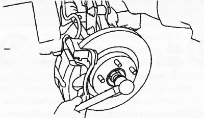
6. Disconnect the ball joint of the tie rod end from the steering knuckle.
7. Loosen the upper nut of the anti-roll bar and disconnect the anti-roll bar from the suspension strut.
8. If equipped, remove the dynamic damper.
9. Remove the brake hose clamp.
10. Disconnect the ball joint of the lower suspension arm.
11. Install the spare nut onto the drive shaft threads so that the edge of the nut is flush with the end of the drive shaft.
12. Tap the nut with a brass hammer to knock the drive shaft out of the front wheel hub.
13. Disconnect the drive shaft from the wheel hub.
14. Using a special tool, disconnect the left drive shaft from the gearbox.
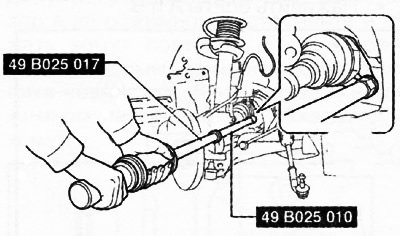
Caution: Be careful not to damage the gearbox seal.
15. Remove the retaining ring from the left drive halyard.
16. Loosen the mounting nuts and remove bracket No.2 of the right drive shaft.
17. Remove the right drive shaft in the same way as removing the left drive shaft.
18. Diesel versions only: Remove the exhaust manifold bracket.
19. Loosen the mounting bolts and remove bracket No.1 of the right drive shaft.
20. Installation is carried out in the reverse order of removal, taking into account the following:
Installing the drive shaft lock
Install the new retaining ring into the groove on the end of the drive shaft with the connector facing up.
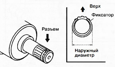
After installation, measure the outer diameter of the retainer. If the measured value exceeds 34 mm, repeat the installation using a new retainer ring.
Installing the right drive shaft
Tighten the threaded studs to a torque of 8-11 Nm.
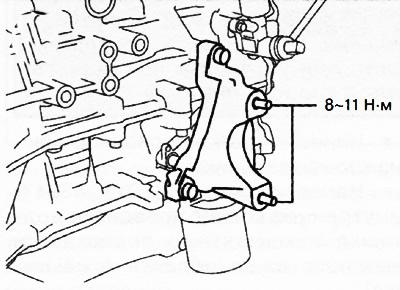
Caution: Tighten the threaded studs only when the bracket #2 mounting nuts are loosened.
Tighten bolts A and B.
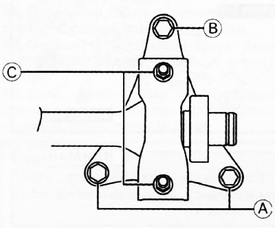
First tighten bolts A to a torque of 42-62 Nm, and then bolt B to a torque of 42-62 Nm.
Insert the drive shaft into the gearbox until the drive shaft bearing contacts the bracket stop.
Fit nuts C and then tighten to a torque of 22-28 Nm.
Apply transmission oil to the seal lips.
Apply lubricant (L2Y1 33247) on the inner ring of the wheel bearing and the contact surface of the drive shaft (area A in the figure).
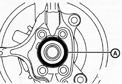
Insert the drive shaft into the wheel hub.
Insert the drive shaft into the gearbox.
After installation, pull the outer race of the drive shaft from the gearbox side towards you to ensure that the retainer securely holds the drive shaft.
Installing the left drive shaft
Caution: Sharp edges on the drive shaft can cut or puncture the seal. Use caution when installing the drive shaft into the transmission.
Apply transmission oil to the seal lips.
Apply lubricant (L2Y1 33247) on the inner ring of the wheel bearing and the contact surface of the drive shaft (area A in the figure).
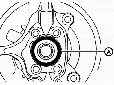
Insert the drive shaft into the wheel hub.
Insert the drive shaft into the gearbox.
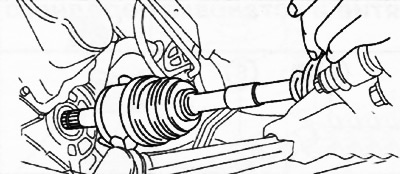
After installation, pull the outer race of the drive shaft from the gearbox side towards you to ensure that the retainer securely holds the drive shaft.
Tightening the drive shaft lock nut
After tightening the lock nut to a torque of 390 Nm, unscrew it by 180 degrees, then tighten it again to a torque of 236-274 Nm.