


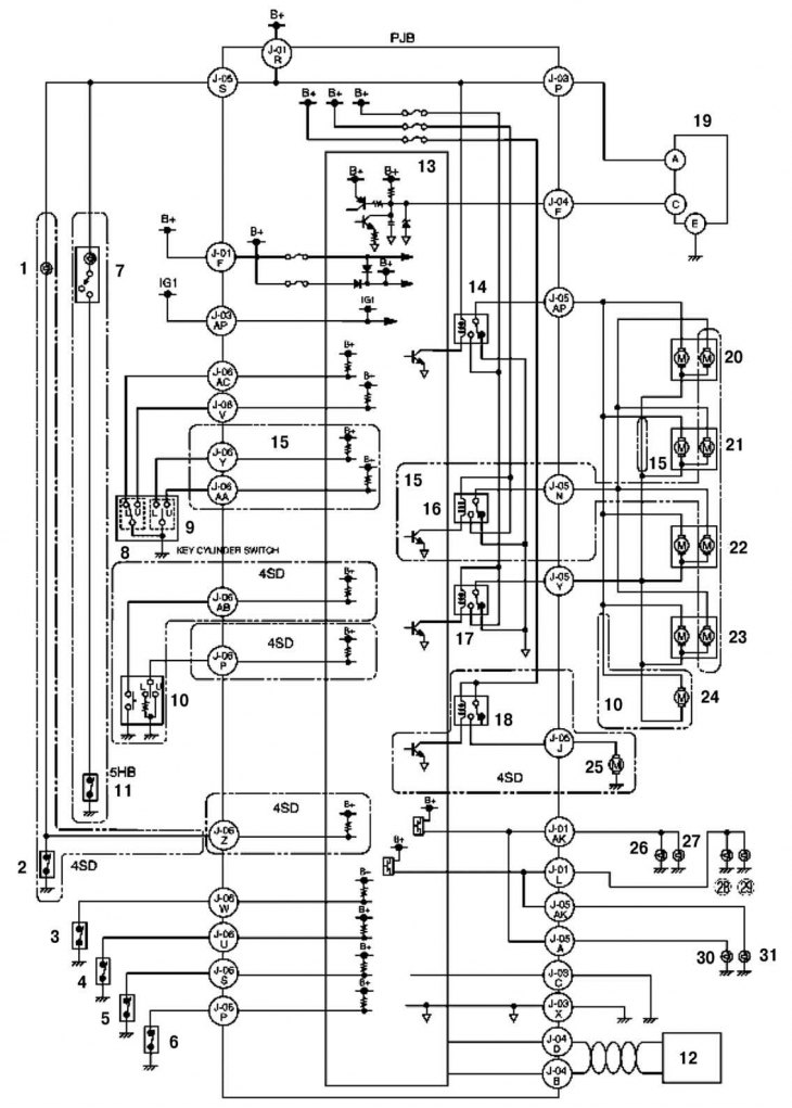
Fig. 8.33. Wiring diagram of the remote door lock control system: 1 – Engine compartment light; 2 – trunk lid lock switch; 3 – Front door lock switch (left); 4 – Front door lock switch (right); 5 – rear door lock switch (left); 6 – rear door lock switch (right); 7 – luggage compartment light; 8 – door lock pull switch; 9 – Front door lock cylinder switch; 10 – trunk lid lock cylinder switch; 11 – Tailgate lock switch; 12 – instrument cluster; 13 – microcomputer; 14 – door lock relay; 15 – with double locking function; 16 – double-circuit relay; 17 – door unlock relay; 18 – trunk lid release relay; 19 – Remote control unit for door locks; 20 – front door lock actuator (driver side); 21 – front door lock actuator (passenger side); 22 – rear door lock actuator (left); 23 – rear door lock actuator (right); 24 – tailgate lock actuator; 25 – trunk lid lock actuator; 26 – Front direction indicator (left); 27 – side direction indicator (left); 28 – Front direction indicator (right); 29 – side direction indicator (right); 30 – rear direction indicator (left); 31 – rear turn signal (right)
The control unit and the door lock timer unit are combined. The radio transmitter is equipped with a button to turn off the alarm sensor. The lock cylinder switch is located in the door lock retainer.
Original version of the article on the website: www.MAZbook.ru