
Attention! When fixing the steering bracket in a vise, place copper plates on the jaws of the vise, place a rag or similar material on it.
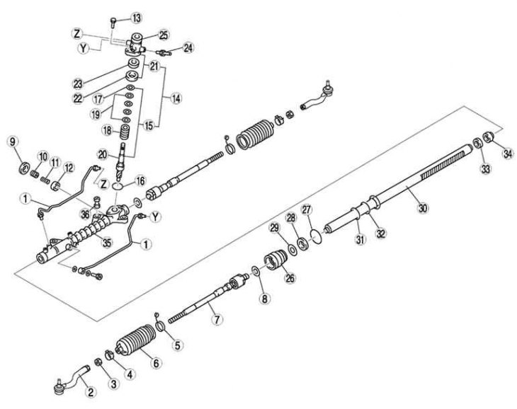
Pic. 5.16. Steering gear and tie rod components: 1 - hydraulic system pipeline; 2 – a tip of steering draft; 3 - locknut; 4 – a collar of a protective cover; 5 - tape collar of the protective cover; 6 - protective cover; 7 – steering draft; 8 - washer; 9 - locknut (adjusting cover); 10 - adjusting cover; 11 - rail stop spring; 12 - rail stop; 13 - bolt; 14 - gear shaft and housing; 15 - gear shaft; 16 - sealing ring; 17 - retaining ring; 18 - control valve; 19 - ring seal; 20 - gear shaft; 21 - valve body; 22 - upper bearing; 23 - stuffing box; 24 - return pipeline; 25 - valve body; 26 - holder; 27 - sealing ring; 28 - U-shaped gasket; 29 - support ring; 30 - steering rack; 31 - ring seal; 32 - sealing ring; 33 - stuffing box; 34 - inner guide; 35 – the case of the steering mechanism; 36 - rubber support
The components of the steering mechanism and steering rods are shown in fig. 5.16.