
Note: carrying out repair operations without first removing the wheel speed sensor (ABS) may damage the sensor wiring. To prevent damage to the sensor or its wiring, remove the wheel speed sensor and secure it out of the way before making major repairs.
1. (Models with ABS) Remove the front wheel speed sensors (see chapter "Brake system").
2. Remove the parts in the order they are numbered on the assembly drawing "Removal and installation of the steering gear and rods".
Note:
- Installation is made in an order, the return to removal.
- After installation, check and, if necessary, adjust the toe-in of the front wheels (see chapter "Suspension").
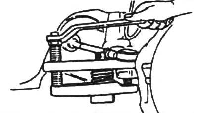
Removal note
Using a special puller, disconnect:
- outer tie rod end from steering knuckle:
- inner tie rod end from central link;
- ball bearing of the intermediate lever from the central thrust;
- bipod ball joint from the central link.
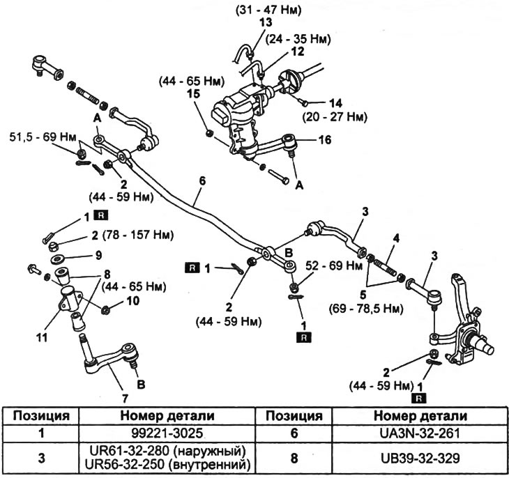
Removal and installation of the steering gear and rods.
1 - cotter pin,
2 - nut,
3 - tie rod end,
4 - steering rod,
5 - locknut,
6 - central thrust,
7 - intermediate lever,
8 - bushing,
9 - washer,
10 - bolt, nut and washer,
11 - intermediate lever bracket,
12 - injection tube,
13 - return tube,
14 - bolt,
15 - bolt, nut and washer,
16 - steering gear and bipod assembly.