


Contents: Preliminary checks ⇓ Checking and adjusting the…⇓ Checking and adjusting wheel angles ⇓ Checking the wheel alignment and…⇓ Adjusting the camber and…⇓ Checking and adjusting the alignment ⇓
Preliminary checks
1. The vehicle must be parked on a level surface when unloaded.
Note: * - the fuel tank is fully filled, the engine has the set level of coolant and oil, the spare wheel, jack and standard tool kit are in place.
2. Check the tire type and tire pressure. If the pressure is not correct, adjust the pressure (see the "Tires and Wheels" table).
Table. Tires and wheels.
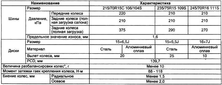
Note: * - the weight of one weight should not exceed 60 g, the weight of weights on one side should not exceed 120 g. There should not be more than two weights on one side.
3. Check the axial clearance of the front wheel hub bearings. If necessary, adjust the axial clearance of the bearings.
4. Check the runout of the wheels and tires.
5. Check for significant wear in the ball joints and steering rod connections.
6. After rocking the car, check the operation of the shock absorbers.
Checking and adjusting the suspension height
Note: Before adjusting the suspension angles, be sure to first adjust the suspension height. Changing the suspension height may cause changes to other suspension angles that have already been adjusted.
1. Conduct preliminary checks.
2. Place the vehicle on a level horizontal surface.
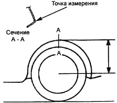
3. Measure the distance from the wheel center to the lower edge of the wing on both sides. The difference between the two measurements should not exceed 10 mm.
- Height - 502 - 542 mm
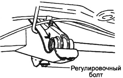
If necessary, adjust the front suspension height by turning the adjusting bolt.
Note: Turning the adjusting bolt one full turn changes the suspension height by 3.3mm.
Checking and adjusting wheel angles
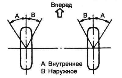
1. Place the vehicle on a wheel alignment stand and check the maximum wheel turning angles.
Note: If a portable alignment stand is used for adjustment, the rear wheels are placed on a stand so that the car is level.
Wheel turning angles:
- Inner — 31°30' - 35°30'
- External - 27°00' - 32°00'
2. Adjust the wheel angles if necessary.
a) Remove the hub cover.
b) Loosen the adjusting bolt lock nut.
c) Turn the adjusting bolt to adjust the wheel turning angles.
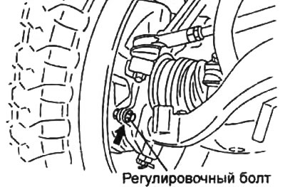
d) Tighten the adjusting bolt lock nut.
- Tightening torque - 39 - 59 Nm
d) Install the hub cover.
Checking the wheel alignment and longitudinal tilt of the steering axis
1. Rock the car up and down several times to stabilize the suspension.
2. Measure the wheel alignment and caster angle.
- Camber — 0°45' ±1°mm
- Longitudinal tilt of the rotation axis - 2°06' ±1°mm
Adjusting the camber and longitudinal tilt of the steering axis
1. Loosen the front suspension upper arm axle bolt.
2. To adjust the angles, select the thickness of the adjusting spacers.
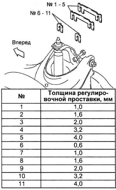
Note:
- Do not install more than two spacers (No. 1-5) on one side.
- Do not install more than one spacer (No. 6-11) on one side.
- To adjust the camber, use spacers #1-5. Adding/removing one 1mm thick spacer decreases/increases the camber by 15'.
- To adjust the longitudinal tilt of the steering axis, spacers No.6-11 are used:
- Adding one 1mm spacer to the front or removing one from the rear increases the pitch by 30'.
- Adding one 1mm spacer to the rear or removing one from the front reduces the pitch by 30'.
3. Tighten the front suspension upper arm pivot bolt.
- Tightening torque - 150 - 172 Nm
Checking and adjusting the alignment
1. Rock the car up and down several times to stabilize the suspension.
2. Measure the toe-in value.
- Nominal value - 6±3 mm
3. Adjust the front wheel alignment if necessary.
a) Set the front wheels to the straight ahead position.
b) Loosen the tie rod end lock nuts.
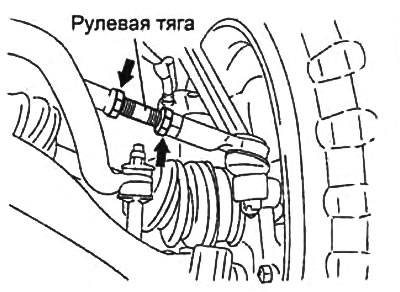
c) Adjust the toe-in by rotating the steering rods.
d) When adjusting, turn both steering rods by the same angle. Both rods have right-hand threads. When turning the right rod clockwise, the left rod must be turned counterclockwise.
[The text of the article is taken from the website: MAZbook.ru]
Note: Turning both rods one full turn changes the toe-in value by approximately 30 mm.
d) Tighten the tie rod end locknuts.
- Tightening torque - 69 - 79 Nm