
Removal and installation
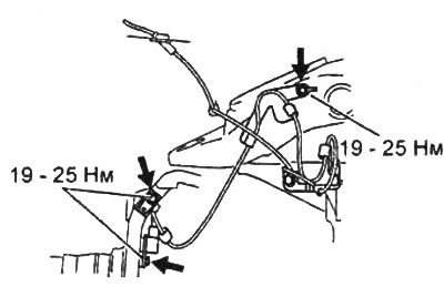
Note: carrying out repair operations without first removing the wheel speed sensor (ABS) may damage the sensor wiring. To prevent damage to the sensor or its wiring, remove the wheel speed sensor and secure it out of the way before making major repairs.
1. Remove the wheel speed sensor and sensor brackets.
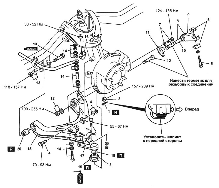
2. Remove the parts in the order of their numbering in the assembly drawing "Removal and installation of the torso and the lower arm of the front suspension".
Note:
- Installation is made in an order, the return to removal.
- After installation:
- check and, if necessary, adjust the height of the front suspension;
- check and, if necessary, adjust the angles of the front suspension.
Removal and installation of the torsion bar and the lower arm of the front suspension.
1 - cotter pin,
2 - nut,
3 - ball joint of the lower arm of the front suspension,
4 - bolt and nut for fastening the lower part of the shock absorber,
5 - adjusting bolt,
6 - hinge nuts,
7 - bolt and washer,
8 - torsion bar assembly,
9 - anchor lever,
10 - torchon,
11 - support bracket,
12 - bolt, nut and washer of the rear mounting of the lever,
13 - bolt, nut and washer of the front mounting of the lever,
14 - bolt, bushing, spacers and anti-roll bar nut,
15 - lower front suspension arm,
16 - front suspension stroke limiter,
17 - ball joint of the lower arm of the front suspension,
18 - retaining ring,
19 - anther,
20 - front bushing.
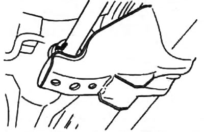
Withdrawal Notes
1. Anchor lever bolt.
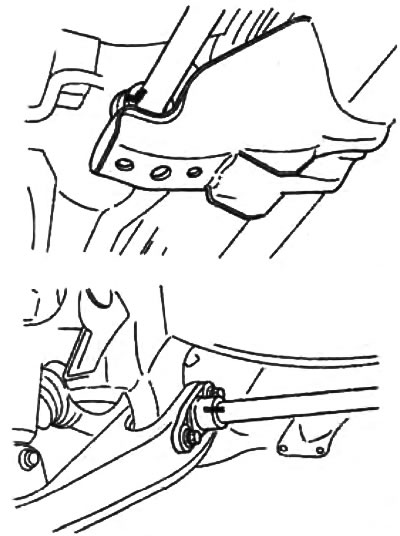
Mark the anchor arm and body before loosening the anchor arm bolt.
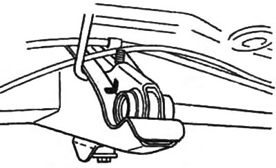
2. Torsion.
Before removing the torsion bar, mark the torsion bar and anchor arm, torsion bar and support bracket.
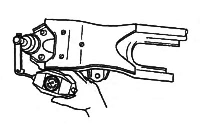
3. Front hub.
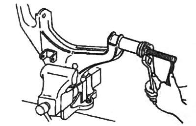
Using a puller, remove the front bushing from the lower arm.
Installation Notes
1. Front hub.
Note: Do not reuse the removed bushing.
A) For ease of installation, apply soapy water to the new front hub.
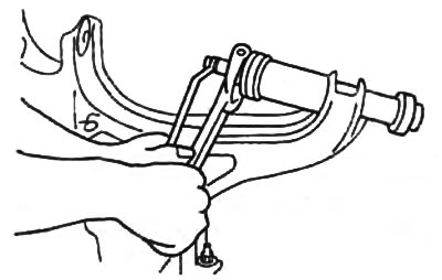
b) Using the special tool, install the new front bushing into the lower arm.
2. Torsion.
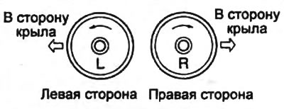
A) For proper installation, check the marks on the ends of the torsion bars and install the torsion bars in accordance with the marks. Label "L" denotes left side, label "R" - right.
b) Align the marks on the torsion bar and support bracket and install the torsion bar.
3. Anchor lever.
Align the marks on the anchor arm and torsion bar and install the anchor arm.
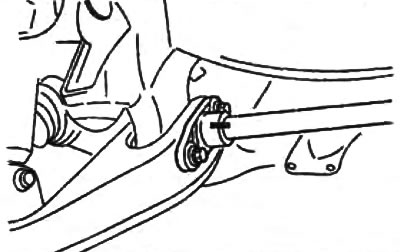
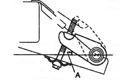
4. Anchor arm adjusting bolt.
Tighten the adjusting bolt until the marks on the anchor arm and body line up.
If the marks were not applied during removal or a new anchor lever is installed, then:
- Load the front suspension until the top arm contacts the suspension travel stop.
- Tighten the adjusting bolt so that the corner "A" in the range 55°30' - 64°30'.
Examination
1. Remove the lower front suspension arm from the vehicle.
2. Check up absence of damages, cracks and curvature on the lever.
3. Make sure that there is no excessive play in the ball joint of the lever.
4. Check up the moment of resistance to rotation of a finger of a spherical support.
A) Rotate the ball joint pin five times.
b) Install a special tool on the ball joint pin and measure the resistance to rotation with a dynamometer.
- Dynamometer readings - 20 - 34 N
If the measured resistance is not correct, replace the lever assembly.