Contents: Disassembly notes ⇓ Assembly Notes ⇓
Remove the parts in the order they are numbered in the assembly drawing "Steering gear".
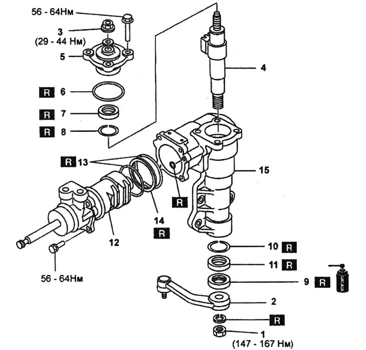
Steering gear.
1 - nut,
2 - steering knuckle,
3 - nut,
4 - sector shaft,
5 - cover,
6 - O-ring seal,
7 - thrust ring,
8 - retaining ring,
9 - oil seal,
10 - retaining ring,
11 - thrust ring,
12 - valve and piston assembly,
13 - O-ring seal,
14 - O-ring seal,
15 - steering gear housing.
Note:
- Installation is carried out in the reverse order of removal.
- After assembly, adjust the steering gear play.
Based on website data [www.MazBook.ru]
Disassembly notes
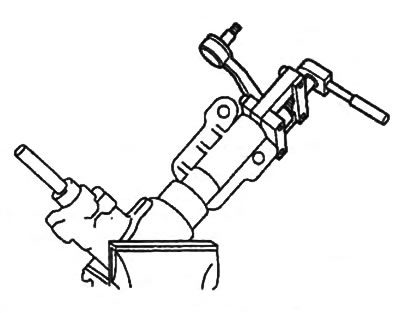
1. Steering arm.
Using a special puller, remove the steering arm from the steering gear.
2. Sector shaft.
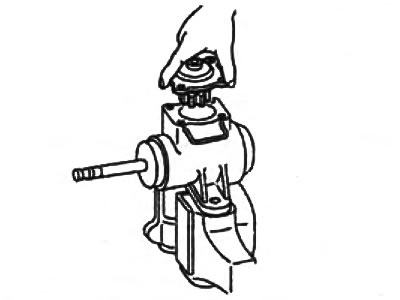
a) Loosen the shaft mounting nut.
b) Unscrew the cover mounting bolts.
c) Set the sector shaft to the middle position.
d) Using a plastic hammer, knock out the sector shaft from the bottom side.
d) Remove the sector shaft assembly with the cover and nut.
Assembly Notes
Valve and piston
Note:
- Be careful not to damage the piston O-rings during installation.
- When installing, rotate the valve and piston slightly to the right and left to avoid crushing the O-rings.
a) Install the valve assembly with the piston into the steering gear.
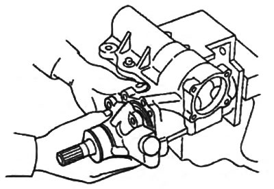
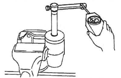
b) Using a special device and a dynamometer, measure the resistance to rotation of the worm shaft.
- Torque of resistance to rotation - 0.64 - 1.23 Nm
- Dynamometer readings: 6.4 - 12.3 N