


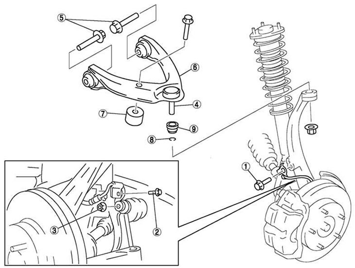
Fig. 4.22. Upper arm of the front suspension: 1 – bolt (anti-lock brake system wheel speed sensor); 2 – bolt (brake hose bracket); 3 – nut (stabilizer link); 4 – front upper ball joint of the lever; 5 – bolt (front Upper Control Arm); 6 – Front upper arm; 7 – dynamic damper; 8 – clamp; 9 – protective cover
The upper arm of the front suspension is shown in Fig. 4.22.
Removal
Support the steering knuckle using a jack.
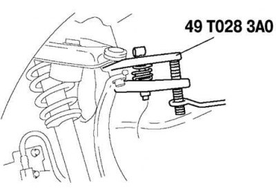
Fig. 4.23. Separating the ball joint from the swivel joint
Based on website data MazBook.ru
Separate the ball joint from the steering knuckle using a special tool (Fig. 4.23).
Remove the three nuts on the top of the front shock absorber.
Remove the front shock absorber and coil spring towards the outside of the vehicle.
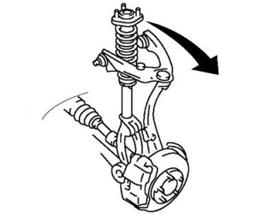
Fig. 4.24. Removing the front upper arm
Loosen the mounting bolts and remove the front upper arm (Fig. 4.24).
Examination
Check the lever for damage, cracks and deformation.
Check the moment of resistance to rotation of the ball joint.
Rotate the ball joint pin five turns.
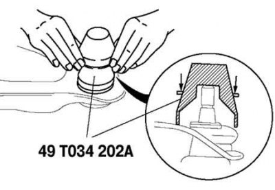
Fig. 4.25. Checking the moment of resistance to rotation of the ball joint
Measure the torque using a suitable socket and torque wrench (Fig. 4.25).
If the measurement result is different from the norm, replace the lower arm assembly.
Maximum moment of resistance: 1.5 Nm.
Installation
Wipe off any grease from the ball joint.
Fill the inside of the new boot with grease.
Install the cover on the ball joint.
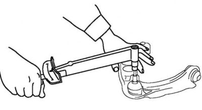
Fig. 4.26. Installing a new ball joint boot clamp
Install the new clamp using the special tool (Fig. 4.26).
Make sure the clamp is securely seated in the groove.
Wipe off any remaining grease.
Install the remaining components in the reverse order of removal.