


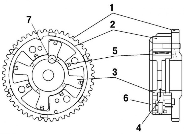
Fig. 2.36. Design of the variable valve timing mechanism: 1 – camshaft sprocket; 2 – body; 3 – rotor; 4 – pin; 5 – seal; 6 – lid; 7 – groove
The variable valve timing actuator consists of a housing combined with the camshaft sprocket, a cover, a rotor combined with the camshaft, and a pin that determines the relative position of the rotor and housing when the engine is stopped. In addition, the rotor has a seal that isolates the advance section and the retard section of the valve opening or closing. The cover and rotor of the variable valve timing actuator have grooves that are used for proper alignment when inspecting the variable valve timing actuator (Fig. 2.36).
For details, see the website www.MazBook.ru