


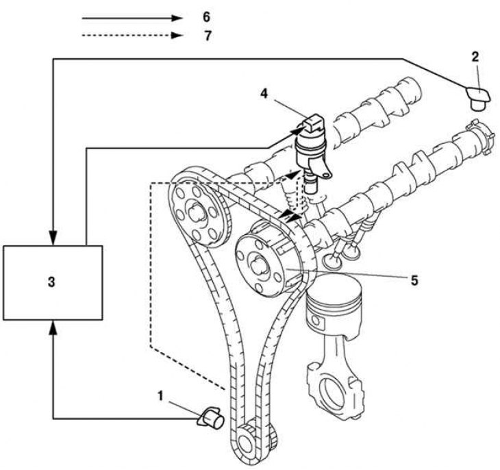
Fig. 2.31. Structural diagram of the valve timing mechanism: 1 – crankshaft position sensor; 2 – camshaft position sensor; 3 – PCM block; 4 – Oil control valve (OCV); 5 – actuator for changing valve timing; 6 – electrical signal; 7 – hydraulic pressure
The variable valve timing mechanism consists of an actuator, an oil control valve (OCV), a crankshaft position sensor, a camshaft position sensor and a PCM (fig. 2.31, 2.32 and Table 2.12).
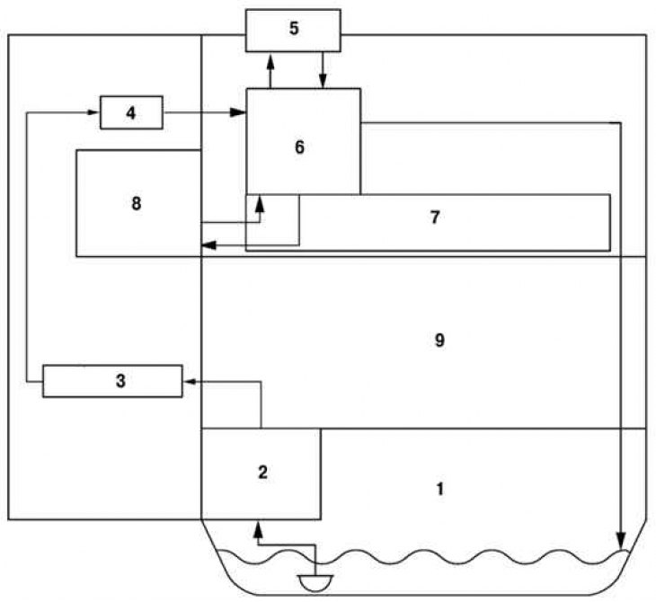
Fig. 2.32. Block diagram of the hydraulic pressure system: 1 – oil pan; 2 – oil pump; 3 – oil pipeline; 4 – oil filter; 5 – Oil control valve (OCV); 6 – Oil Control Valve (OCV) Adapter; 7 – camshaft; 8 – actuator for changing valve timing; 9 – cylinder block