


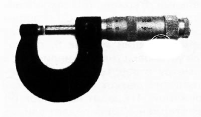
A micrometer is a device designed for measuring linear dimensions using the absolute contact method in the area of small dimensions with high accuracy (from 0.01 to 0.001 mm), the conversion mechanism of which is a screw-nut micropair.
It is necessary to keep the micrometer clean. Be careful not to drop the micrometer, as its bracket may become deformed, which will lead to inaccurate measurements.
The operation of the micrometer is based on the movement of the screw along the axis when it rotates in a fixed nut. The movement is proportional to the angle of rotation of the screw around the axis. Full turns are counted on the scale applied to the stem of the micrometer, and fractions of a turn - on the circular scale applied to the drum. The optimal movement of the screw in the nut is only a length of no more than 25 mm due to the difficulty of manufacturing a screw with an accurate pitch over a greater length. Therefore, the micrometer is made in several standard sizes for measuring lengths from 0 to 25 mm, from 25 to 50 mm, etc. For micrometers with measurement limits from 0 to 25 mm, with closed measuring planes of the heel and the micrometer screw, the zero mark of the drum scale must exactly coincide with the longitudinal mark on the stem, and the beveled edge of the drum - with the zero mark of the stem scale. To measure lengths greater than 25 mm, a micrometer with replaceable heels is used; setting such micrometers to zero is done using a setting measure applied to the micrometer or end measures. The item being measured is clamped between the measuring planes of the micrometer. Usually the pitch of the screw is 0.5 or 1 mm and, accordingly, the scale on the stem has a division value of 0.5 or 1 mm, and 50 or 100 divisions are applied to the drum to obtain a reading of 0.01 mm. This reading value is the most common, but there are micrometers with a reading of 0.005, 0.002 and 0.001 mm. A constant axial force when the screw contacts the item is provided by a friction device - a ratchet. When the measuring surfaces of the micrometer are in close contact with the surface of the item being measured, the ratchet begins to turn with a slight crack, and the rotation of the microscrew should stop after three clicks.
When taking measurements, the object (2) is clamped between the heel and the micrometer screw (3). On the surface of the stem there are two line scales, offset relative to each other by 0.5 mm, and having a division value of 1 mm. The drum (7) rotates around the circular scale, which is also located on the bevel of the drum. The micrometer screw can be fixed in any position. The screw is equipped with a ratchet mechanism to ensure the constancy of the measuring pressure.
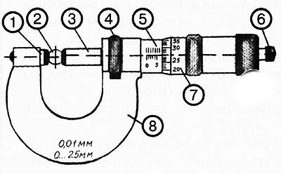
1. Heel.
2. Subject of measurement.
3. Spindle.
4. Wheel.
5. Measuring scale (in mm).
6. Ratchet.
7. Drum vernier.
8. Bracket.
1. The object is placed between the heel and the micrometer screw, while rotating the drum, the spindle is set to the approximate size of the object.
(Information copied from the portal: MAZbook.ru)
2. The spindle is carefully moved until it comes into contact with the object being measured.
3. The size in mm is determined using the drum vernier, which corresponds to the horizontal index line of the stem scale.
4. The overall size of the measured object is determined.
Note: When in contact with the measured object, do not tighten the spindle by rotating the drum sleeve by hand, this may cause the micrometer to break. For more accurate measurement, make sure that the object is well secured.