
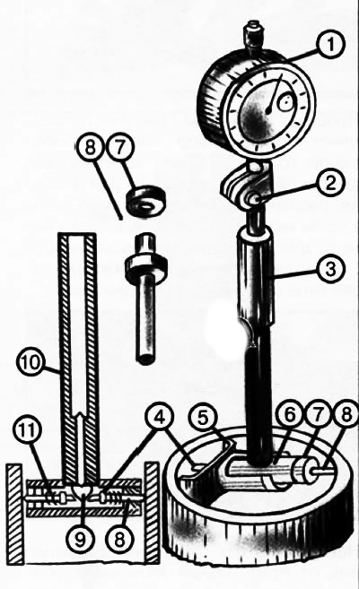
1. Dial indicator.
2. Screw.
3. Handle.
4. Engine.
5. Centering bridge.
6. Tee.
7. Nut.
8. Measuring rod.
9. Fungus.
10. Rod.
11. Coil spring.
The device has a guide bush (5), in the upper part of which a dial indicator is installed (1), screw fixed (2). Inside the sleeve is a long rod that is in contact with a short rod (10), resting on the fungus (9) tee (6) caliper heads. The engine is located in the tee (4) and interchangeable measuring rod (8), fixed in the tee with a nut (7). On the side of the movable pin on the tee, a centering bridge 5 is mounted, which serves to install the indicator head along the diameter of the hole. When measuring holes, the slider (4) with coil spring (11) crushes the fungus (9) and through the rod (10) transfers the movement to a long rod to the indicator.
The deviation of the size is determined by the movement of the indicator arrow. Before measurement, the inside gauge is set to the nominal size along the ring or block of tiles.
Indicator calipers are produced with measurement limits: 6-10; 10-18; 18-35; 35-50; 50-100; 100-160; 160-250; 250-450 mm. For measurement, interchangeable washers and rods are attached to the inside gauge, differing from each other by 1 or 5 mm (depending on the measurement limit). The washers are installed in the hole of the head tee.