


Contents: Removal ⇓ Installation ⇓
Caution: Performing the following procedures without first removing the ABS wheel speed sensor may cause an open circuit in the wiring harness if the harness is accidentally tightened.
Caution: Remove the ABS wheel speed sensor before performing the following operations (from the hub side) and fix it in a suitable place where the sensor will not be damaged by mistake during maintenance.
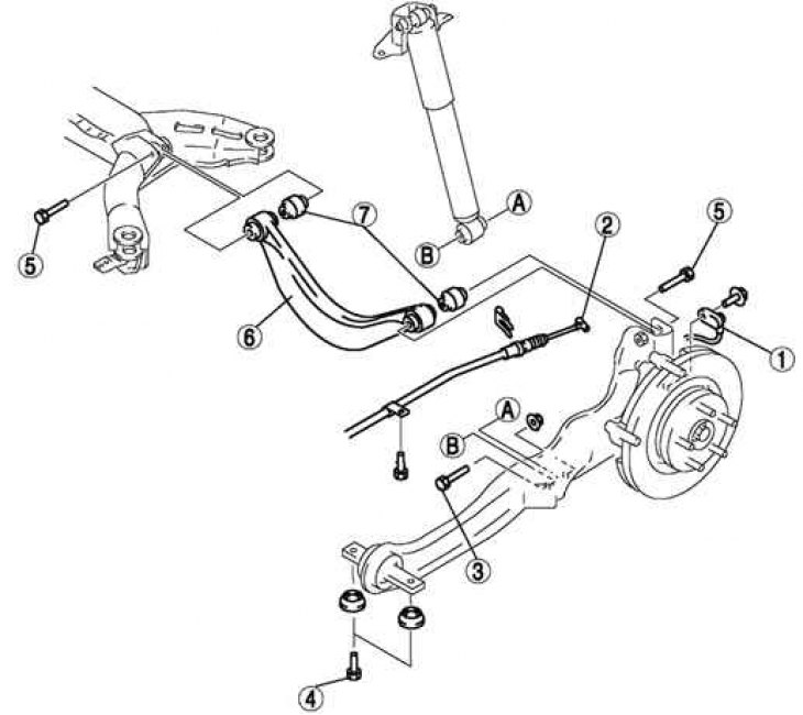
Fig. 4.32. Rear upper arm: 1 – Anti-lock braking system wheel speed sensor; 2 – parking brake cable; 3 – bolt (lower part of the rear shock absorber); 4 – bolt (front part of the longitudinal rod); 5 – bolt (rear upper control arm); 6 – rear upper arm; 7 – rear upper arm bushing
Removal
Remove the anti-lock brake system wheel speed sensor.
Disconnect the parking brake cable.
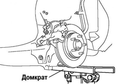
Fig. 4.33. Installing a jack under the longitudinal traction
Support the longitudinal rod with a jack (Fig. 4.33).
Loosen the bolts on the inner and outer sides of the tie rod.
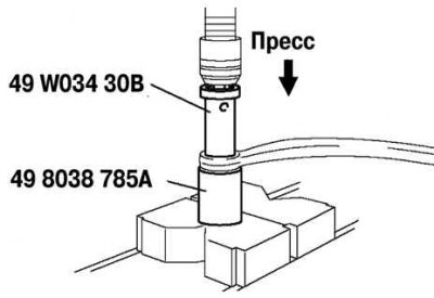
Fig. 4.34. Pressing out the upper arm bushing
Press out the upper arm bushing using special tools (Fig. 4.34).
Installation
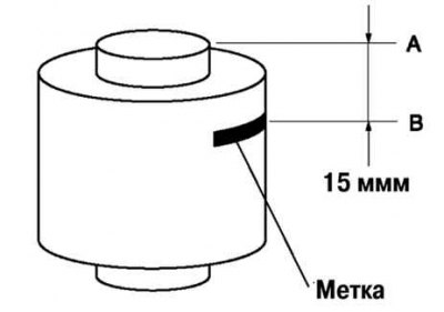
Fig. 4.35. Marking the new bushing
Mark the new bushing as shown in Figure 4.35.
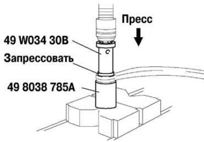
Fig. 4.36. Pressing in a new upper arm bushing
(Based on website data: «Mazbook.ru»)
Press the bushing in according to the marking using special tools (Fig. 4.36).
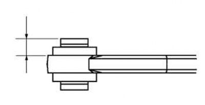
Fig. 4.37. Checking the height of the pressed bushing
Check that the distance AB is 14.0 mm - 16.0 mm (Fig. 4.37).
Install the remaining components in the reverse order of removal.