


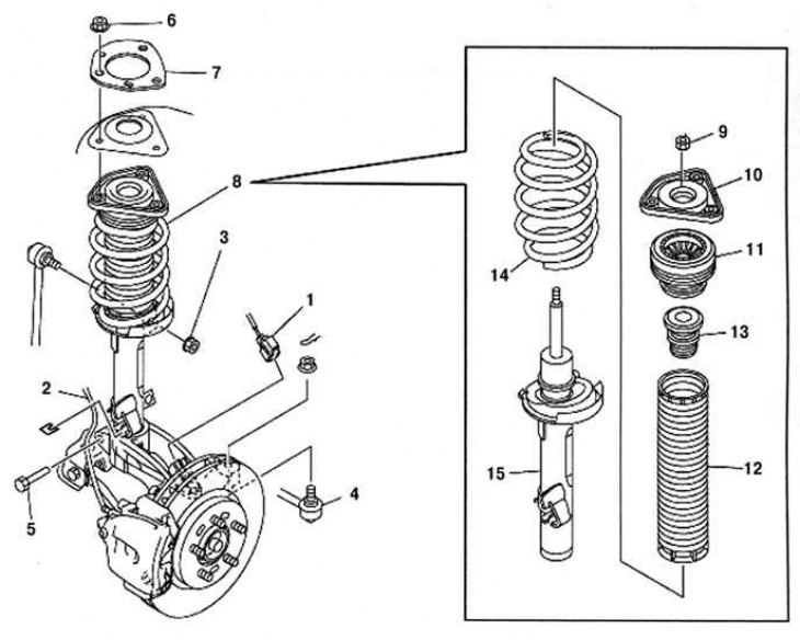
Fig. 4.11. Front shock absorber strut components: 1 – ABS wheel speed sensor wiring harness connector; 2 – brake hose; 3 – upper nut of the stabilizer bar; 4 – steering rod end; 5 – lower shock absorber bolt; 6 – upper shock absorber nut; 7 – stiffening element; 8 – shock absorber and coil spring; 9 – piston rod nut; 10 – rubber support; 11 – bearing; 12 – protective cover; 13 – compression stroke buffer; 14 – cylindrical spring; 15 – front shock absorber
Removal
Loosen the wheel speed sensor mounting bolt.
Loosen the brake hose bracket mounting bolt.
Unscrew the stabilizer strut mounting nut and the lower shock absorber mounting bolt.
Remove the dynamic damper.
Loosen the shock absorber fork mounting bolt.
Loosen, but do not completely remove, the three nuts securing the upper shock absorber strut cover.
Remove the shock absorber assembly and fix it on a special stand.
Cover the spring with cloth and install special devices.
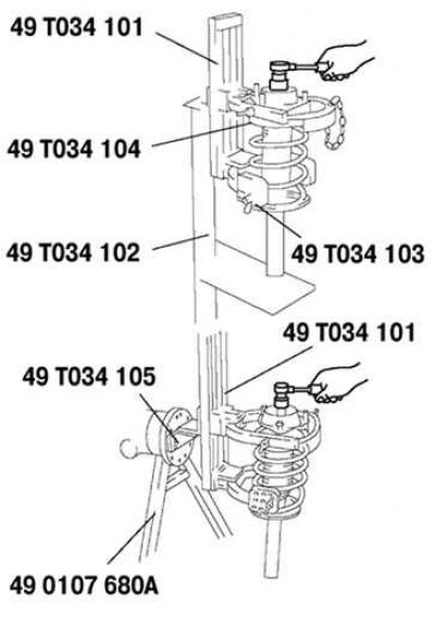
Fig. 4.12. Removing the shock absorber rod mounting nut
Compress the spring using the device and unscrew the shock absorber rod mounting nut (Fig. 4.12).
Examination
Check the shock absorber for damage and oil leaks.
Check the rubber bushing for any signs of damage or wear.
Extend and retract the shock absorber piston rod at least three times. Make sure that the resistance force does not change and there is no unusual noise.
If there is a fault, replace the shock absorber.
Press the shock absorber piston rod down and release it.
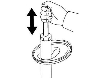
Fig. 4.13. Checking the free travel of the shock absorber rod
The original article is posted on (MazBook)
Make sure the piston rod extends fully at normal speed (Fig. 4.13).
Installation
Temporarily install the coil spring, boot and rubber mount on the shock absorber so that the bottom edge of the coil spring fits over the protrusion of the lower spring cup.
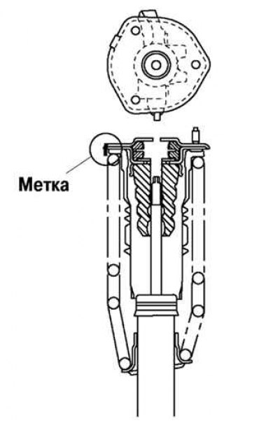
Fig. 4.14. Shock absorber strut component markings
Mark the coil spring, boot and rubber support for proper installation as shown in Fig. 4.14.
Align the marks of the coil spring and the protective boot. Wrap the coil spring and protective boot with a piece of cloth, then install the special tools.
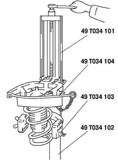
Fig. 4.15. Compression of a cylindrical spring
Compress the coil spring using special tools (Fig. 4.15).
Install the shock absorber so that the lower edge of the coil spring fits on the protrusion of the lower spring cup.
Make sure the marks on the shock absorber and the protective cover match.
Install the rubber support and piston rod nut, then remove the special tools.
Piston rod nut tightening torque: 39.2–52.9 N·m.
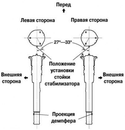
Fig. 4.16. Installing threaded studs
Install the threaded studs at an angle of 27-33° relative to the stabilizer bar (center line), towards the inside of the car (Fig. 4.16).
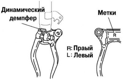
Fig. 4.17. Installing the shock absorber fork
Install the shock absorber fork and align it with the marks together with the dynamic damper (Fig. 4.17).
Tighten the fork mounting bolt.
Install the remaining components in the reverse order of removal.