- The local area network of the CAN controller is used.
- A mechanical fuel system is used without fuel return to the tank.
- An intake manifold management system is used to improve engine performance in the high-speed range (l3 engine).
- The variable valve timing system is used to improve engine performance (l3 engine).
- A variable intake system is used to increase engine torque and combustion efficiency (l3 engine).
- The fuel injection control system performs correction based on the absolute pressure in the intake manifold.
- The system has a non-adjustable ignition timing angle.
- All fuel line connections are equipped with quick-release connectors.
- The KOEO/KOER self-diagnosis function is used.
- The process of storing raw codes has been changed.
- The MIL indicator operating mode has been changed for the second type of driving cycle.
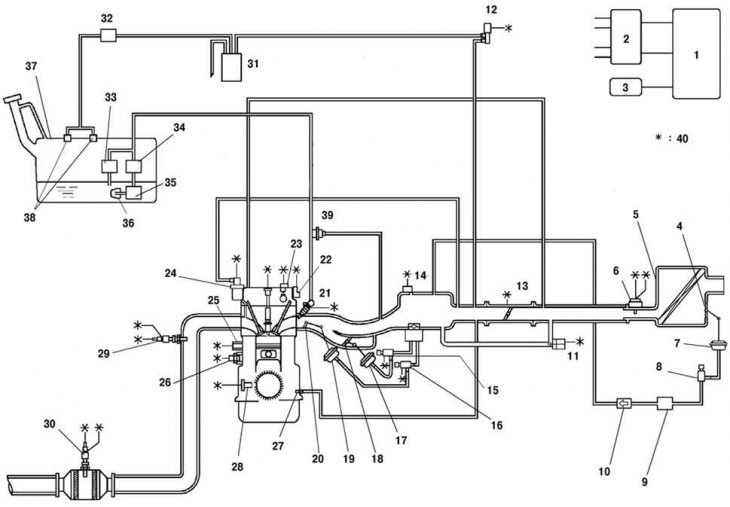
Fig. 2.53. Diagram of the fuel system control system of the Mazda 6 car: 1 – PCM block; 2 – ignition coil; 3 – generator; 4* – VAD system damper; 5 – air filter; 6 – mass air flow sensor; 7* – actuator of the VAD system damper; 8* – VAD system control solenoid valve; 9* – vacuum chamber; 10* – VAD system check valve; 11 – idle speed control; 12 – purge electromagnetic valve; 13 – throttle position sensor; 14 – absolute pressure sensor; 15* – VIS system control solenoid valve; 16 – Variable tumble control solenoid valve; 17* – actuator of the VIS system damper; 18* – VIS system valve; 19 – actuator of the VTCS valve; 20 – VTCS valve; 21 – fuel injector; 22* – control oil valve; 23 – camshaft position sensor; 24 – exhaust gas recirculation valve; 25 – knock sensor; 26 – coolant temperature sensor; 27 – crankcase ventilation valve; 28 – crankshaft position sensor; 29 – Heated oxygen concentration sensor (front); 30 – Heated oxygen concentration sensor (rear); 31 – container with activated carbon (adsorber); 32 – check valve (double-sided); 33 – pressure regulator; 34 – fuel filter (high pressure); 35 – fuel pump; 36 – fuel filter (low pressure); 37 – fuel tank; 38 – gravity valve; 39 – pulsation damper; 40 – to the PCM block; Note – *: for L3 engines
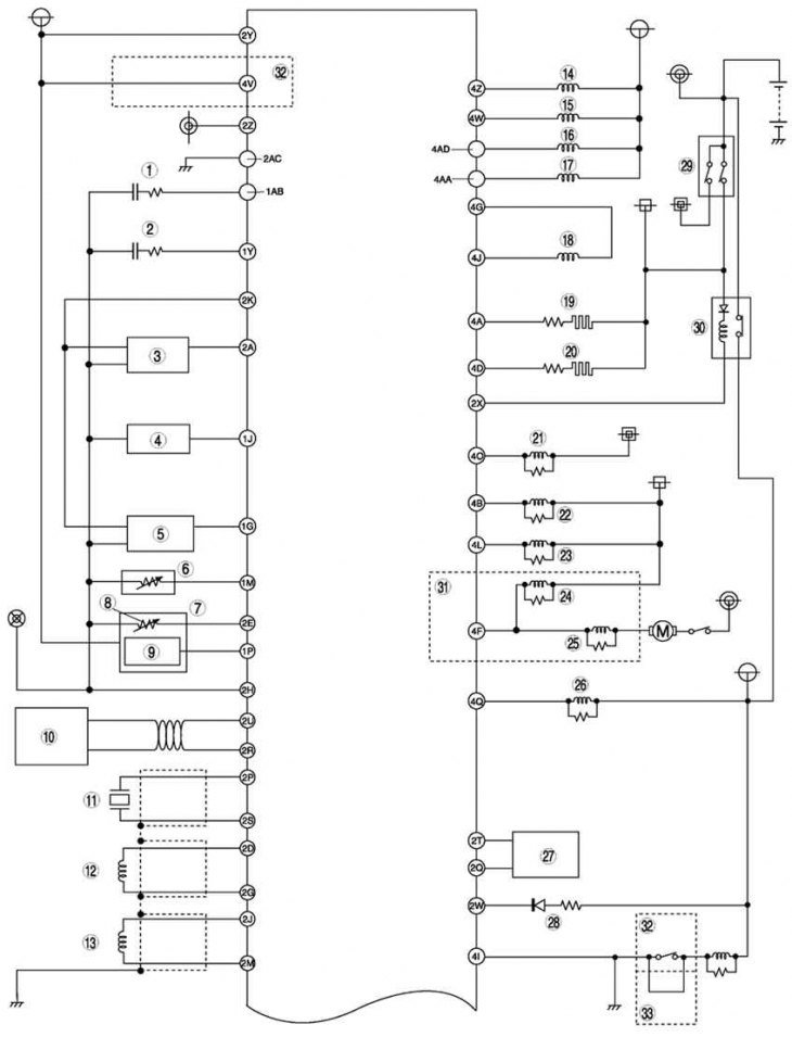
Fig. 2.54a. Wiring diagram of the fuel system control system of the Mazda 6 with an immobilizer (part 1)
Fuel management system of the Mazda 6 with immobilizer (fig. 2.54a, 2.54b) contains the following elements: 1 – heated oxygen concentration sensor (front); 2 – heated oxygen concentration sensor (rear); 3 – throttle position sensor; 4 – absolute pressure sensor in the intake manifold; 5 – pressure sensor; 6 – coolant temperature sensor; 7 – Mass air flow/intake air temperature sensor; 8 – intake air temperature sensor; 9 – absolute pressure sensor in the intake manifold; 10 – Controller Area Network (CAN); 11 – knock sensor; 12 – crankshaft position sensor; 13 – camshaft position sensor; 14 – fuel injector No.1; 15 – fuel injector No.2; 16 – fuel injector No.3; 17 – fuel injector No.4; 18 – idle speed control; 19 – Oxygen concentration sensor heater (front); 20 – Oxygen concentration sensor heater (rear); 21 – Air conditioning system relay; 22 – Cooling system fan relay; 23 – Cooling system fan relay; 24 – Cooling system fan relay; 25 – Cooling system fan relay; 26 – fuel pump relay; 27 – spiral; 28 – safety lamp; 29 – ignition switch; 30 – main relay; 31 – L8, LF engines (hot area) and L3; 32 – models with automatic transmission; 33 – models with manual transmission; 34 – generator; 35 – refrigerant pressure sensor (middle); 36 – Power steering pressure sensor; 37 – Fan motor; 38 – refrigerant pressure sensor (high and low); 39 – Air conditioning system switch; 40 – Brake light switch; 41 – neutral switch; 42 – Clutch switch; 43- Gearbox range switch; 44 – turbine speed sensor; 45 – HOLD switch; 46 – TFT sensor; 47 – oil pressure sensor; 48 – vehicle speed sensor; 49 – ignition coil; 50 – generator; 51 – purge electromagnetic valve; 52 – VAD system control solenoid valve; 53 – exhaust gas recirculation valve; 54 – Variable tumble control solenoid valve; 55 – VIS system control solenoid valve; 56 – control oil valve; 57 – valve body; 58 – brake signal; 59 – L8, LF engines (hot area) and L3; 60 – model with manual transmission; 61 – models with automatic transmission; 62 – engine L3
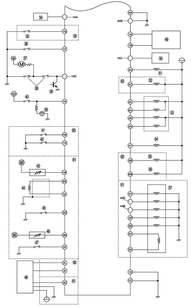
Fig. 2.54b. Wiring diagram of the fuel system control system of the Mazda 6 with an immobilizer (part 2 – continued)
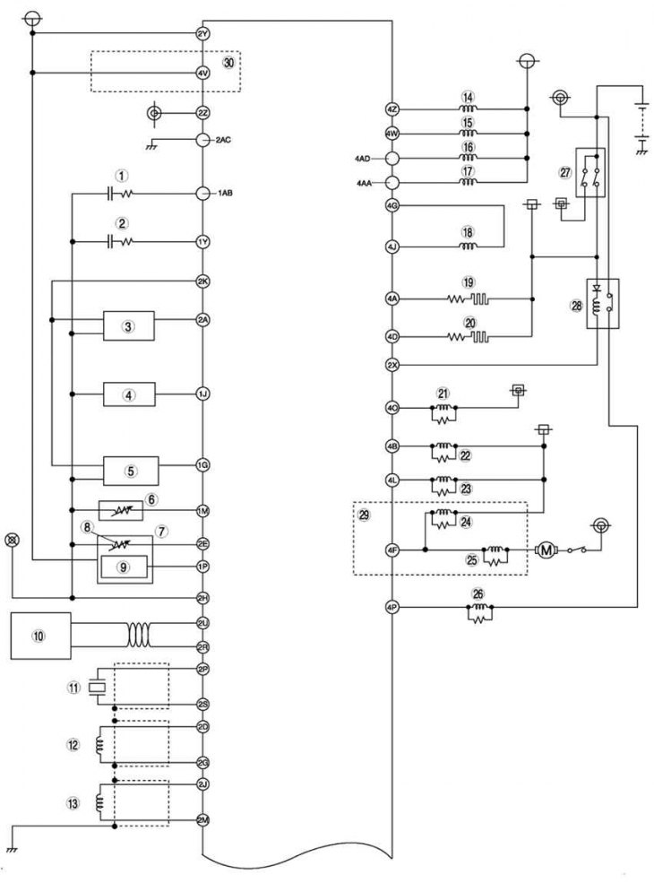
Fig. 2.55a. Wiring diagram of the fuel system control system of a Mazda 6 without an immobilizer (part 1)
Fuel management system of Mazda 6 car without immobilizer (fig. 2.55a, 2.55b) contains the following elements: 1 – heated oxygen concentration sensor (front); 2 – heated oxygen concentration sensor (rear); 3 – throttle position sensor; 4 – absolute pressure sensor in the intake manifold; 5 – pressure sensor; 6 – coolant temperature sensor; 7 – Mass air flow/intake air temperature sensor; 8 – intake air temperature sensor; 9 – absolute pressure sensor in the intake manifold; 10 – Controller Area Network (CAN); 11 – knock sensor; 12 – crankshaft position sensor; 13 – camshaft position sensor; 14 – fuel injector No.1; 15 – fuel injector No.2; 16 – fuel injector No.3; 17 – fuel injector No.4; 18 – idle speed control; 19 – Oxygen concentration sensor heater (front); 20 – Oxygen concentration sensor heater (rear); 21 – Air conditioning system relay; 22 – Cooling system fan relay; 23 – Cooling system fan relay; 24 – Cooling system fan relay; 25 – Cooling system fan relay; 26 – fuel pump relay; 27 – ignition switch; 28 – main relay; 29 – L8, LF engines (hot area) and L3; 30 – models with automatic transmission; 31 – generator; 32 – refrigerant pressure sensor (middle); 33 – Power steering pressure sensor; 34 – fan motor; 35 – refrigerant pressure sensor (high and low); 36 – Air conditioning system switch; 37 – Brake light switch; 38 – brake signal; 39 – neutral switch; 40 – clutch switch; 41 – Gearbox range switch; 42 – Input/Turbine Speed Sensor; 43 – HOLD switch; 44 – TFT sensor; 45 – oil pressure sensor; 46 – vehicle speed sensor; 47 – oil pressure sensor; 48 – vehicle speed sensor; 48 – generator; 49 – purge electromagnetic valve; 50 – VAD system control solenoid valve; 51 – exhaust gas recirculation valve; 52 – Variable tumble control solenoid valve; 53 – VIS system control solenoid valve; 54 – oil control valve; 55 – valve body; 56 – L8, LF engines (hot area) and L3; 57 – models with manual transmission; 58 – models with automatic transmission; 59 – L3 engine.
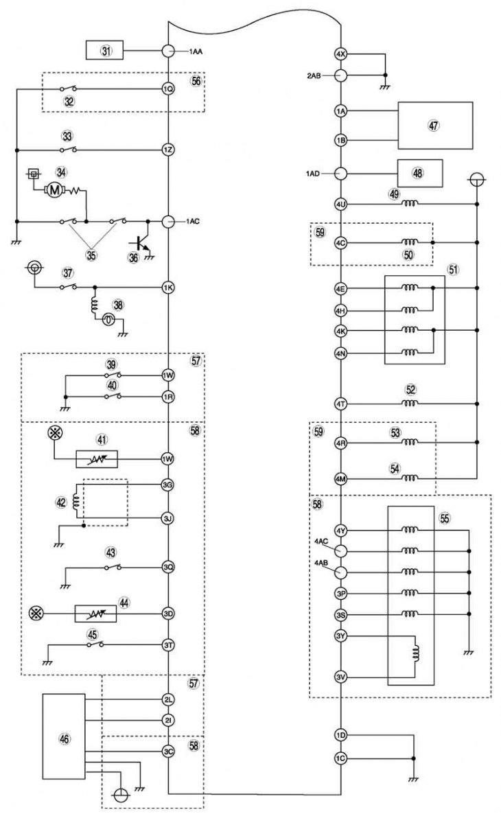
Fig. 2.55b. Wiring diagram of the fuel system control system of a Mazda 6 car without an immobilizer (part 2 – continued)
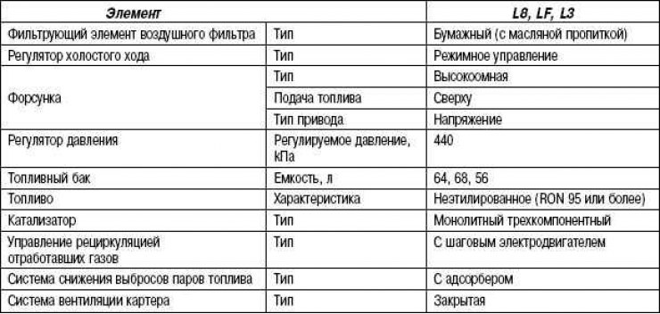
Table 2.19. Technical characteristics of the fuel system