
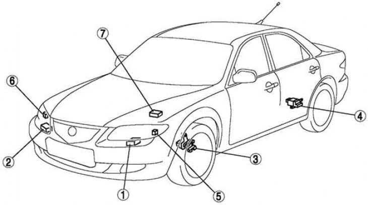
Pic. 7.14. Headlight auto leveling system: 1 - automatic leveling control unit (main); 2 - automatic leveling control unit (additional); 3 - front sensor of automatic leveling; 4 - rear automatic leveling sensor; 5 - headlight leveling actuator (left); 6 - headlight leveling actuator (right); 7 - ABS/TCS HU/CM or DSC HU/CM
The optical axis of the headlights are automatically set at certain angles to improve visibility and prevent dazzling drivers of oncoming vehicles when changing speed or vehicle load.
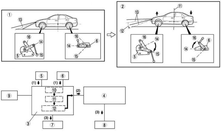
Pic. 7.15. Scheme of the automatic headlight leveling system when changing the vehicle load: 1 - setting to zero; 2 - increase in loading; 3 - automatic leveling control unit (main); 4 - automatic leveling control unit (additional); 5 - front automatic leveling sensor; 6 - rear automatic leveling sensor; 7 - headlight leveling actuator (left); 8 - headlight leveling actuator (right); 9 – ABS/TCS HU/CM or DSC HU/CM; 10 – difference between two voltage signals; 11 - the spatial position of the car; 12 – optical axis adjustment value; 13 – optical axis; 14 - the beginning of the countdown; 15 - high; 16 - low
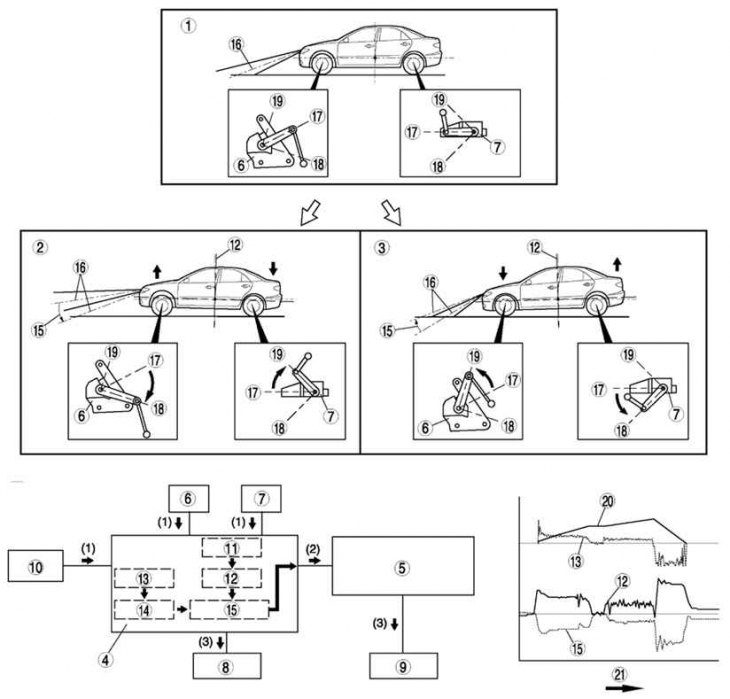
Pic. 7.16. The scheme of the automatic headlight leveling system when the car is moving: 1 - setting to zero; 2 - acceleration; 3 - deceleration; 4 - automatic leveling control unit (main); 5 - automatic leveling control unit (additional); 6 - front automatic leveling sensor; 7 - rear automatic leveling sensor; 8 - headlight leveling actuator (left); 9 - headlight leveling actuator (right); 10 – ABS/TCS HU/CM or DSC HU/CM; 11 – difference between two voltage signals; 12 - the spatial position of the car; 13 - calculation of the acceleration angle; 14 - change in vehicle speed; 15 - the amount of adjustment of the optical axis; 16 - optical axis; 17 - the beginning of the countdown; 18 - high; 19 - low; 20 – vehicle speed; 21 - time