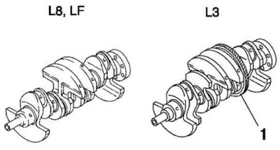
Fig. 2.8. Crankshafts of engines of models L8, LF and L3: 1 – drive gear
The crankshafts of the L8 and LF engines are cast iron, 5-bearing, with 4 counterweights. The crankshaft of the L3 engine is cast iron, 5-bearing, with 8 counterweights. The driving gear of the balance shaft drive is installed on the crankshaft. A regular installation key is not used; the tightening force of the crankshaft pulley bolts ensures the fixation of the crankshaft sprocket. When installing the crankshaft sprocket, it is necessary to use a special device for setting the TDC of the first cylinder (Fig. 2.8).
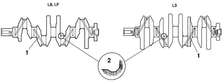
Fig. 2.9. Crankshaft oil passages: 1 – lubrication channel; 2 – fillet
The oil line for supplying oil to the main journals of the crankshaft is located in the crankshaft. The journals and fillets of the crankshaft journals are reinforced by knurling to improve load characteristics.
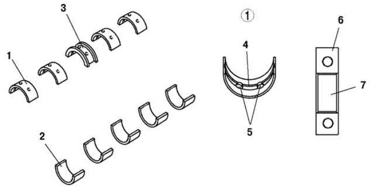
Fig. 2.10. Upper and lower bearing shells and main bearing: 1 – cylinder head mounting bolt; 2 – release side; 3 – inlet side; 4 – front part of the engine; 5 – angle between two valves; 6 – inlet channel; 7 – inlet channel
The upper and lower main bearing shells are made of aluminum alloy. The upper shell of bearing No.3 is a thrust shell. The upper shells have lubrication grooves and oil channels. The upper and lower shells do not have mounting protrusions. Before installing the upper and lower main bearing shells, they must be measured and installed so that they are located in the center of the bearing cap (Fig. 2.10).
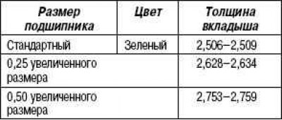
Table 2.2. Types of main bearing shells, mm