


2. Remove the decorative panel.
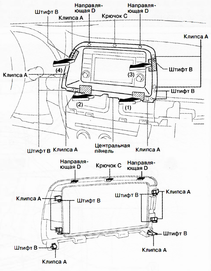
3. Grasp the shaded areas in the figure and pull the central panel in the direction of the arrows in the sequence (1), (2), (3), (4) and remove it by disconnecting the clips A, pins B, hooks C and guides D.
4. Installation is carried out in the reverse order of removal.
Removal and installation the decorative panel
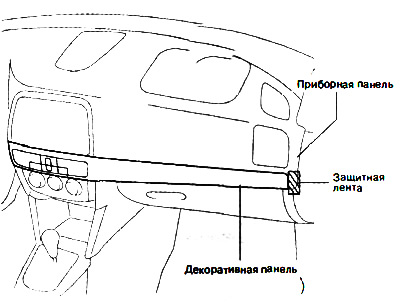
Attention: Apply protective tape to the places indicated in the figure.
1. Disconnect the negative battery terminal.
2. Open the glove compartment.
3. Insert a flat-head screwdriver wrapped with electrical tape into the position indicated by the arrow (1) in the figure and detach clip A.
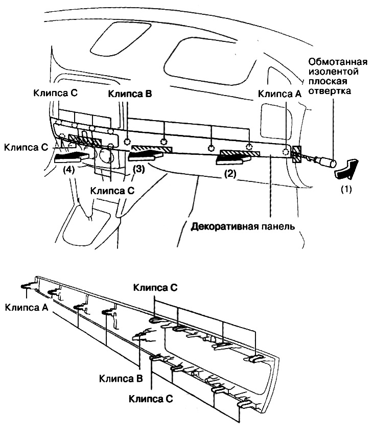
4. Taking hold of the shaded areas in the figure, remove the decorative panel in the direction of the arrows in the sequence (2), (3), (4), disconnecting clips B and C.
5. Disconnect the hazard warning switch connector.
6. Installation is carried out in the reverse order of removal.
Removal and installation the lower instrument panel cover
1. Detach hooks A in the direction of the arrow (1) in the figure.
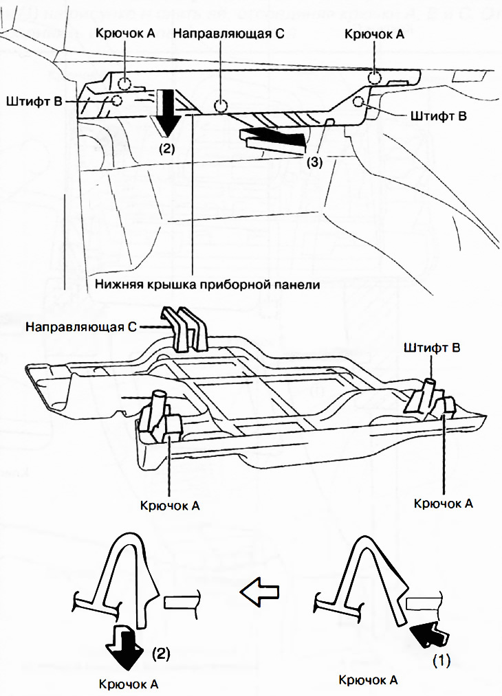
2. Pull the lower instrument panel cover in the direction of the arrow (2) to disconnect pins B.
3. Remove the lower instrument panel cover in the direction of the arrow (3) in the figure to detach the guides C.
Caution: If hooks A and pins B are removed with force, guides C may be damaged. Carefully remove hooks A and pins B to avoid damaging guides C.
4. Installation is carried out in the reverse order of removal.