


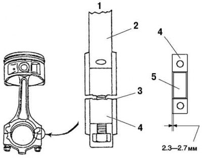
Fig. 2.18. Connecting rod and connecting rod bearing: 1 - extension; 2 – connecting rod; 3 – connector surface; 4 – connecting rod cover; 5 – connecting rod bearing
The connecting rod is made of structured hardened alloy to improve rigidity. The conventional connecting rod bearing locating key is not used. When installing the bearing, measure the bearing position and install it so that it is located in the center of the connecting rod and the connecting rod bearing cap. The lower head and the connecting rod cap are formed as a single element during manufacturing, and then divided into the connecting rod and the cap. Use the split surface configuration to align the connecting rod and the cap. The connecting rod bolt has a tightening torque in the plastic zone, tightening is carried out in two steps. The upper shell of the connecting rod bearing is made of aluminum alloy (Fig. 2.18).
Note: There are three types of connecting rod bearing shells depending on the clearance required.
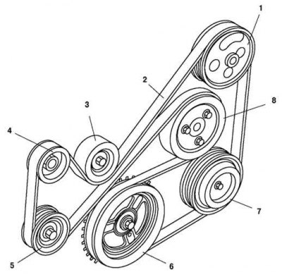
Fig. 2.19. Auxiliary drive belt outline: 1 – power steering pump pulley; 2 – drive belt; 3 – tension pulley; 4 – generator pulley; 5 – automatic tensioner; 6 – crankshaft pulley; 7 – Air conditioning compressor pulley; 8 – coolant pump pulley
The auxiliary drive system uses a single poly V-belt. This reduces the length of the engine and simplifies circuit maintenance. An automatic tensioner with a coil spring is used to tension the belt. The tensioner pulley automatically maintains the tension of the drive belt (2.19).
Table 2.4. Connecting rod bearing shell types (mm)
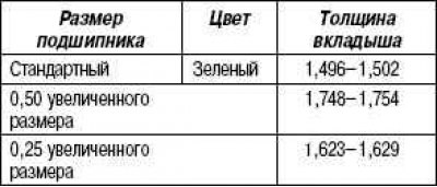
Table 2.5. Drive belt characteristics

* cars without air conditioning