
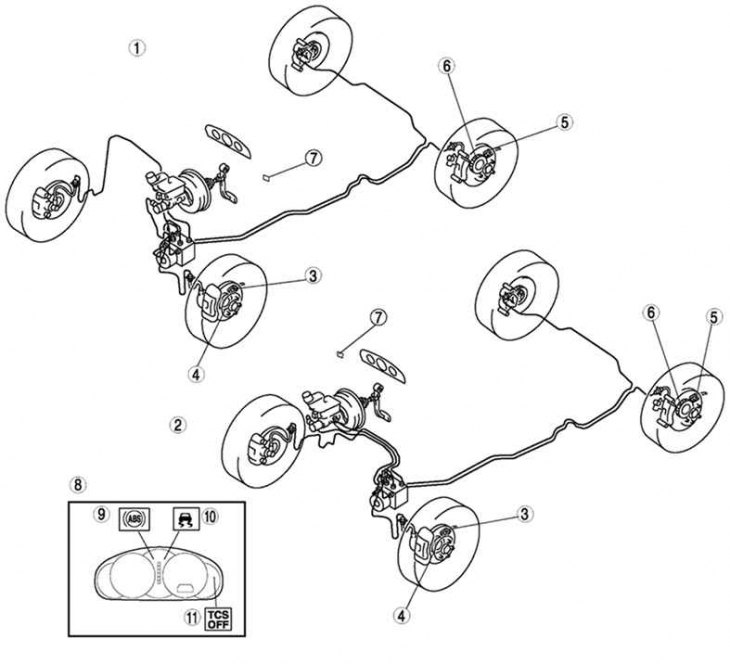
Pic. 6.3. ABS / TCS system of the brake circuit of the Mazda 6: 1 - cars with left-hand steering; 2 - vehicles with right-hand steering; 3 - wheel speed sensor of the anti-lock braking system (front); 4 – a rotor of the gauge of antiblocking system of brakes (front); 5 - wheel speed sensor of the anti-lock braking system (rear); 6 – a rotor of the sensor of antiblocking system of brakes (rear); 7 - TCS system switch; 8 – a combination of devices; 9 – an alarm lamp of antiblocking system of brakes; 10 – a control lamp of the TCS system; 11 – a control lamp of shutdown of the TCS system
Anti-lock braking system (pic. 6.3) limits the pressure generated in the hydraulic brake actuator so that the amount of slip is optimal. The operation of this system must be separate for each wheel. The system must immediately respond to every surface change (adhesion coefficient) and vehicle loads.
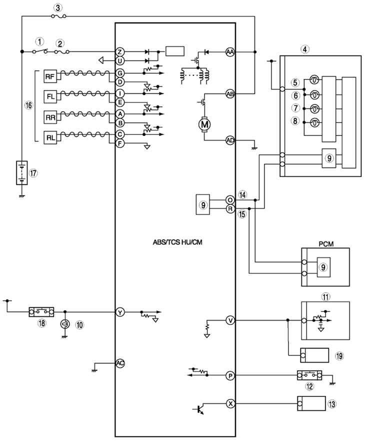
Pic. 6.4. Scheme of the ABS / TCS system of the brake circuit of the Mazda 6: 1 - switch IG; 2 - SUS 15 a (fuse); 3 - anti-lock braking system 60 a (fuse); 4 – a combination of devices; 5 – a lamp of the alarm system of antiblocking system of brakes; 6 – a lamp of the alarm system of brake system; 7 – a control lamp of shutdown of the TCS system; 8 - control lamp TCS (only with TCS system); 9 – CAN driver; 10 - braking signal; 11 - the actuator of the automatic speed control system; 12 - TCS system switch (only with TCS system); 13 - diagnostic connector DLC-2; 14 - CAN-H; 15 - CAN-L; 16 - wheel speed sensor of the anti-lock braking system; 17 - battery; 18 – the switch of signals of braking; 19 - audio unit, switch for windshield wiper and washer, car navigation unit, control unit
The anti-lock braking system prevents the wheels from locking during heavy braking, thereby reducing the braking distance. The grip force between the wheels and the road in this case is greater if the wheels continue to rotate during braking. Even with full braking, the car remains steerable. Speed sensors, one for each wheel, measure wheel speed. Based on sensor signals (see fig. 6.4) The electronic control unit calculates an average speed that approximates the speed of the vehicle. By comparing the rotation speed of each individual wheel with the average calculated speed, the electronic unit determines the slip state of the individual wheel and thereby sets. which wheel is in the pre-lock state.
When one of the four wheel speed sensors transmits a lock signal to the corresponding wheel, the ECU immediately sends a close signal to the corresponding inlet solenoid valve, which shuts off the brake fluid supply through the wheel brake line. In this case, the braking force remains constant. If the sliding continues, the release valve opens and the pressure in the hydraulic system of this brake is reduced. The wheel does not brake, excess brake fluid returns to the reservoir. As soon as the wheel starts spinning again, the intake valve opens and the exhaust valve closes. The pressure in the circuit increases and the wheel brakes again.
The change between braking and free spinning cycles is very fast (several times per second) and continues until the vehicle stops or the brake pedal is released.
The process is repeated under hard braking separately for each wheel until the brake pedal is released.
The emergency system ensures that the ABS is turned off in case of any malfunction or low voltage in the car's on-board network (below 10 V). A faulty ABS does not affect the operation of the brakes.
The hydraulic drive consists of a hydraulic block, brake calipers and brake pipes. The hydraulic unit includes an electric pressure pump and solenoid valves.