
- DSC unit and hydraulic unit are combined for improved serviceability;
- lateral g-sensor and yaw rate sensor combined to improve maintainability;
- brake fluid pressure sensor built into DSC HU/CM;
- DSC HU/CM I/O pins changed;
- electric brake assist is used to improve safety;
- the DSC system switch is used to disable DSC operation;
- the DSC HU/CM system outputs the speed signal to the audio unit, wiper/washer switch, car navigation unit, cruise control actuator and wire leveling control unit, and outputs the speed signal via CAN;
- CAN communication system is used.
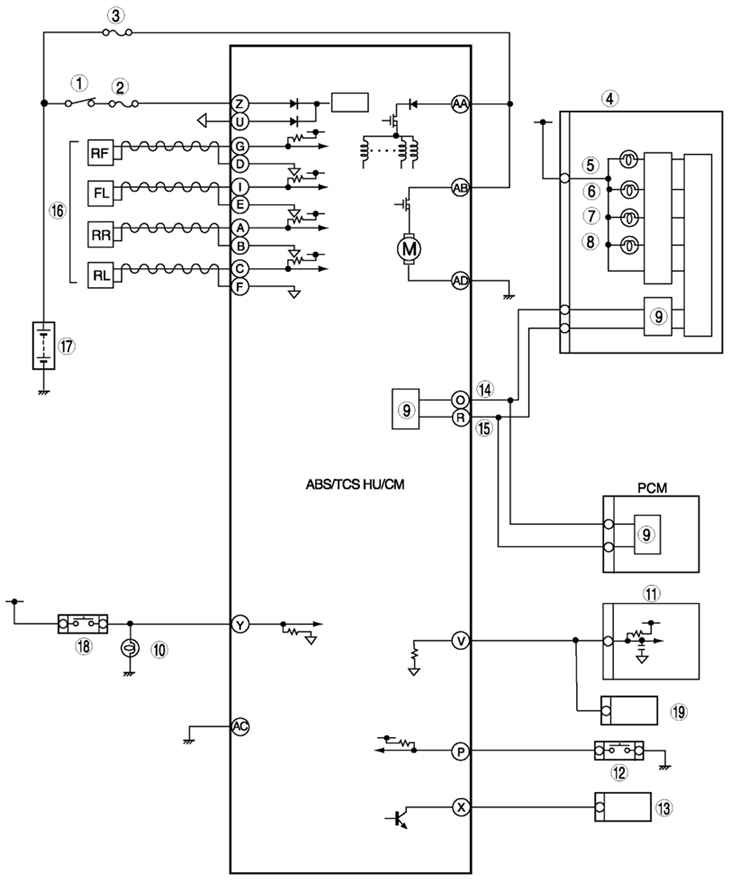
Pic. 6.4. Scheme of the ABS / TCS system of the brake circuit of the Mazda 6: 1 - switch IG; 2 - SUS 15 a (fuse); 3 - anti-lock braking system 60 a (fuse); 4 – a combination of devices; 5 – a lamp of the alarm system of antiblocking system of brakes; 6 – a lamp of the alarm system of brake system; 7 – a control lamp of shutdown of the TCS system; 8 - control lamp TCS (only with TCS system); 9 – CAN driver; 10 - braking signal; 11 - the actuator of the automatic speed control system; 12 - TCS system switch (only with TCS system); 13 - diagnostic connector DLC-2; 14 - CAN-H; 15 - CAN-L; 16 - wheel speed sensor of the anti-lock braking system; 17 - battery; 18 – the switch of signals of braking; 19 - audio unit, switch for windshield wiper and washer, car navigation unit, control unit
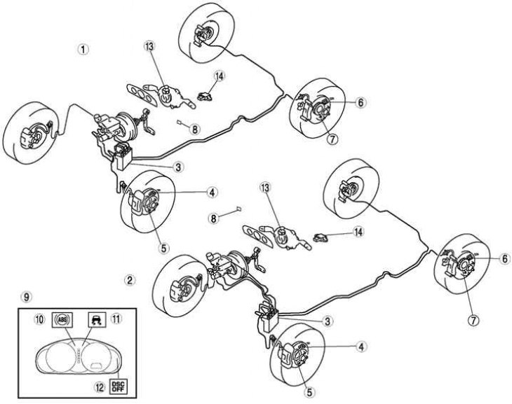
Pic. 6.5. Mazda 6 brake circuit DSC system: 1 - cars with left-hand steering; 2 - vehicles with right-hand steering; 3 – DSC HU/CM; 4 - wheel speed sensor (before); 5 – sensor rotor (before); 6 - wheel speed sensor (rear); 7 – sensor rotor (rear); 8 - DSC system switch; 9 – a combination of devices; 10 – a lamp of the alarm system of antiblocking system of brakes; 11 – a control lamp of the DSC system; 12 – a control lamp of shutdown of the DSC system; 13 – rotation angle sensor; 14 - integrated sensor
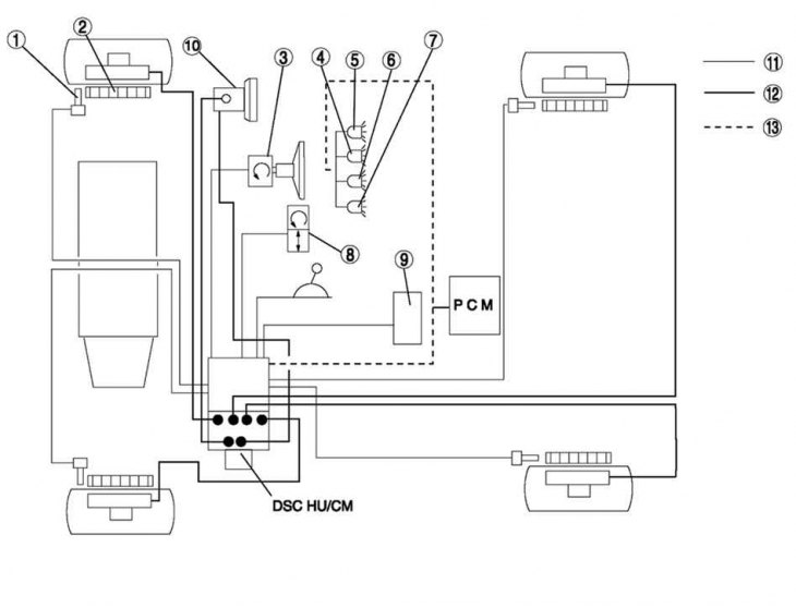
Pic. 6.6. Scheme of the DSC HU / CM system of the Mazda 6 PCM unit: 1 – wheel speed sensor; 2 – sensor rotor; 3 – rotation angle sensor; 4 – a control lamp of the DSC system; 5 – a control lamp of shutdown of the DSC system; 6 – a lamp of the alarm system of brake system; 7 – a lamp of the alarm system of antiblocking system of brakes; 8 - combined sensor; 9 - audio unit, wiper and washer, automatic speed control system actuator, windshield washer switch, car navigation and alignment control unit; 10 - main cylinder; 11 - electrical signal; 12 - brake fluid; 13 - CAN line
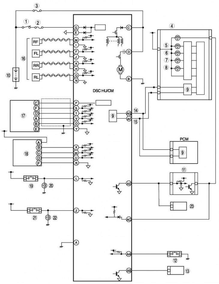
Pic. 6.7. Wiring diagram of the DSC HU / CM system of the Mazda 6 PCM: 1 - switch IG; 2 - fuse SUS 15A; 3 – fuse of anti-blocking system of brakes 60 A; 4 – a combination of devices; 5 – a lamp of the alarm system of antiblocking system of brakes; 6 – a lamp of the alarm system of brake system; 7 – a control lamp of shutdown of the DSC system; 8 – a control lamp of the DSC system; 9 – CAN driver; 10 - battery; 11 - the actuator of the automatic speed control system; 12 - DSC system switch; 13 - diagnostic connector DLC-2; 14 - CAN-H; 15 - CAN-L; 16 - wheel speed sensor; 17 - combined sensor; 18 – rotation angle sensor; 19 – the switch of signals of braking; 20 - braking signal; 21 - reversing light switch (only models with manual transmission); 22 - reversing lamp; 23 - audio unit, switch of the cleaner and washer of glasses, navigation unit, alignment control unit