


Receiving signals from switches and sensors in the input system, the electronic control module (ECM) outputs a signal that matches existing driving conditions to the linear solenoid, shift solenoids, and duty cycle solenoids in the hydraulic control mechanism.
In turn, the hydraulic control mechanism, receiving signals from the PCM unit, switches the hydraulic channels in the control valve block and controls the clutch engagement pressure.
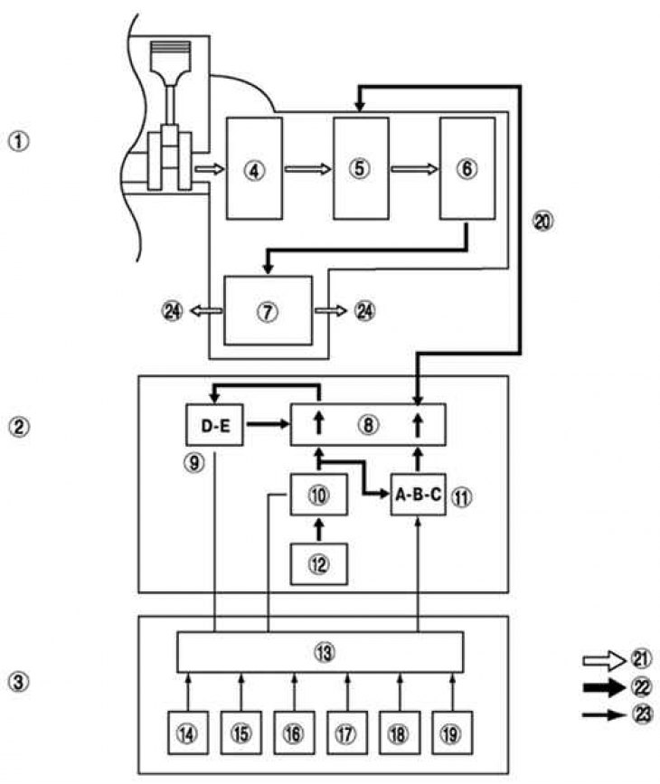
Fig. 3.71. Structural diagram of the operation of the FN4A-EL automatic transmission of the Mazda 6: 1 – transmission mechanism; 2 – hydraulic control mechanism; 3 – electronic control mechanism; 4 – torque converter; 5 – clutches, brakes; 6 – planetary gear; 7 – differential; 8 – control valve block; 9 – switching solenoids D, E; 10 – pressure control solenoid (linear type); 11 – switching solenoids A, B, C (duty cycle solenoids); 12 – oil pump; 13 – RCM block; 14 – oil pressure sensor signal; 15 – vehicle speed; 16 – temperature of the working fluid in the gearbox; 17 – forward clutch drum rotation speed; 18 – engine crankshaft speed; 19 – throttle position signal; 20 – clutch, brake engagement, cut-off pressure; 21 – power flow; 22 – hydraulic pressure control signal; 23 – electronic signal; 24 – wheel
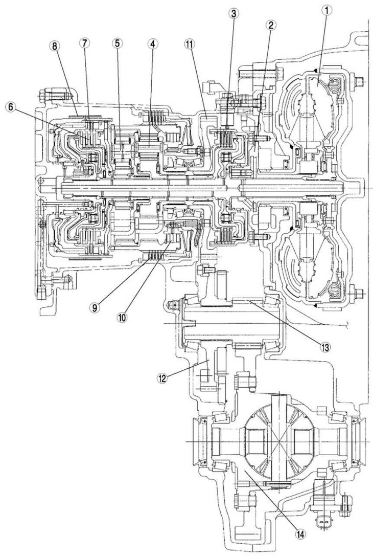
Fig. 3.72. Cross-section of the FN4A-EL automatic transmission of the Mazda 6: 1 – torque converter; 2 – oil pump; 3 – forward clutch; 4 – forward planetary gear; 5 – reverse planetary gear; 6 – clutch 3–4; 7 – reverse gear clutch; 8 – brake band 2–4; 9 – Reverse and low gear brake; 10 – one-way clutch; 11 – primary shaft gear; 12 – secondary shaft gear; 13 – main gear drive pinion; 14 – differential
The pressure in the pipeline is regulated by a linear solenoid. The hydraulic channels are switched by switching solenoids (switching solenoids D and E), the clutch engagement pressure is controlled by the solenoids of the working cycle (shift solenoids A, B, and C) (see fig. 3.71).
In the transmission mechanism, the driving force from the engine is transmitted through the torque converter to the gearbox in the block with the main gear.
The transmitted driving force operates each clutch and brake according to the clutch engagement pressure from the duty cycle solenoids. The planetary gears change the gear ratio to optimize the driving force. The driving force is then transmitted through the differential to the wheel drive shaft and then to the wheels.
Table 3.4. FN4A-EL automatic transmission operation map
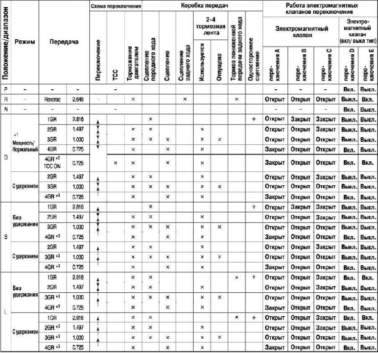
*1 Automatic switches between "power" and "normal" modes according to the speed of pressing the accelerator pedal.
*2 Performs torque converter operation in normal mode.
*3 To prevent engine speed overshoot when downshifting, shifting is delayed until the engine speed drops to the set speed.
x – works
+ – transmits torque only when moving.
Open – switches the pipeline pressure to the clutch pressure.
Closed - Disengages clutch pressure.
On – turns on the output channel and input channel (pressure reducing solenoid).
Off – turns on the outlet channel and drain channel (drain from the outlet channel).