


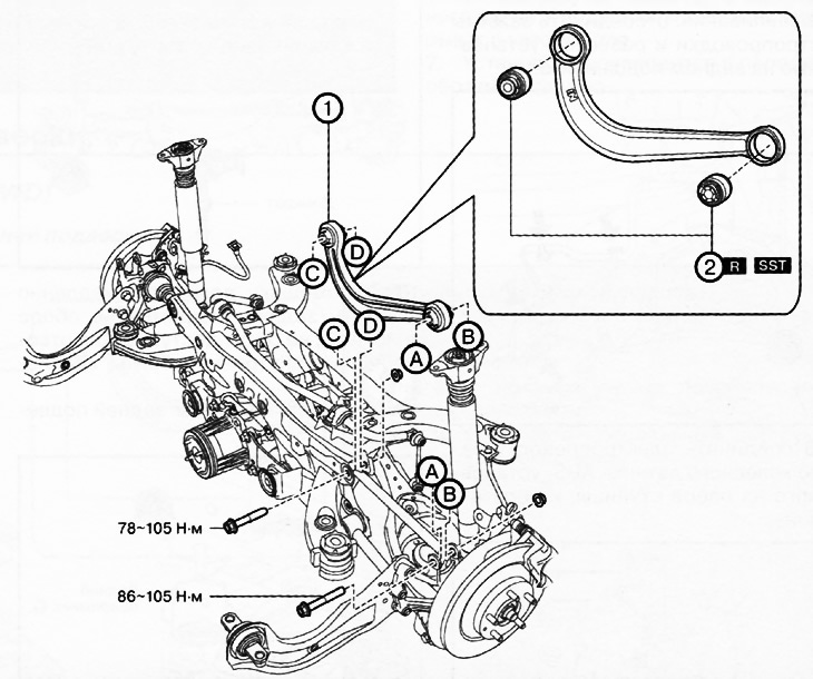
1. Upper arm of the rear suspension.
2. Rear suspension upper arm bushing.
Note:
: replace the part with a new one after each removal.
: use a special tool or device.
Caution: Be careful not to lower the coil spring when removing/installing. Otherwise, the spring may cause serious injury or even death, as well as various damages to the vehicle.
Note:
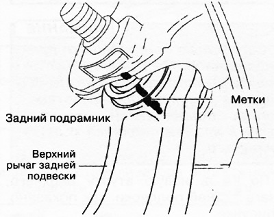
- Before removing the upper rear suspension arm, it is necessary to mark its position.
- When installing, align the marks on the rear subframe and the upper arm of the rear suspension.
- Fully tighten the rear upper control arm inner bolt before installing the rear subframe assembly onto the vehicle.
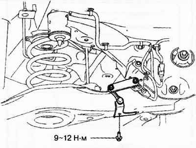
1. Versions with automatic leveling sensor: Working from the left side of the vehicle, disconnect the automatic leveling sensor linkage.
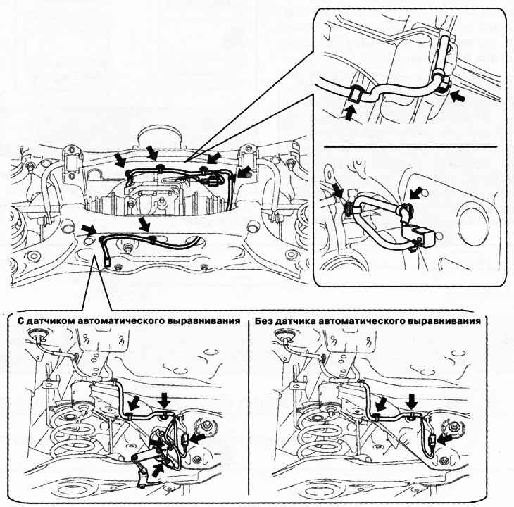
2. Disconnect the electrical wiring clamps and connectors installed on the rear subframe.
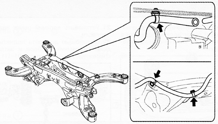
3. Move the rear final drive breather hose to the side.
4. Disconnect the wiring of the rear ABS wheel sensor mounted on the caliper support and set it aside.
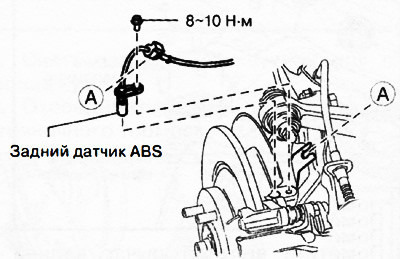
5. Remove the propeller shaft.
6. Remove the three-way catalytic converter.
7. Remove the middle section of the exhaust pipe.
8. Remove the rear suspension coil springs (see section above).
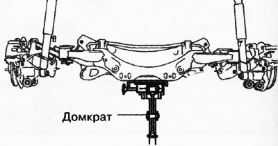
9. Raise the vehicle to relieve the suspension and support the rear suspension trailing arm with a jack.
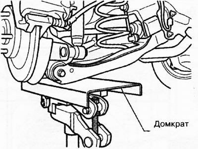
10. Align the rear suspension subframe assembly with the upper suspension arm and apply marks.
11. Support the rear subframe assembly with a jack and unscrew the rear subframe mounting nuts.
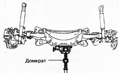
12. Using a jack, slowly lower the rear subframe assembly down until the inner mounting bolts are accessible for removal.
13. Remove the upper rear suspension arm.
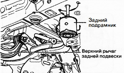
14. Mark the upper rear suspension arm as shown in the figure.
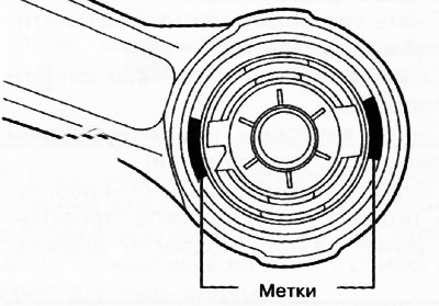
15. Press out the bushings of the upper arm of the rear suspension using special tools.
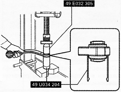
Attention: Using a special device (49 U034 204) install the suspension arm as shown in the figure to prevent damage to the rear suspension upper arm and arm bushing.
16. Mark the new rear upper control arm bushing as shown in the illustration.
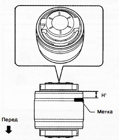
H1: 6.0 mm
17. Align the protrusion of the new rear suspension upper arm bushing with the mark made during removal.
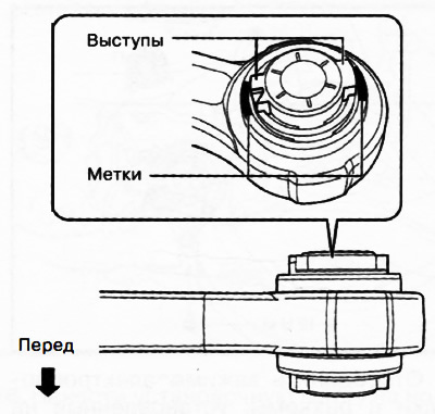
18. Using a special tool, press in the bushing of the upper arm of the rear suspension so that the marks previously applied to the bushing are no longer visible.
Attention: Using a special device (49 U0Z4 204), as shown in the figure, to prevent damage to the rear suspension upper arm and arm bushing, and install the rear suspension upper arm bushing.
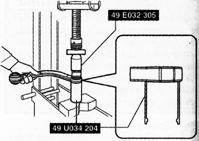
Note: Use caution when pressing the rear upper control arm bushing in place as the height is different on the inside and outside.
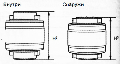
H2: 49.5 mm
H3: 44.5 mm
19. After installing the rear suspension upper arm bushing, make sure it is installed as shown in the figure.
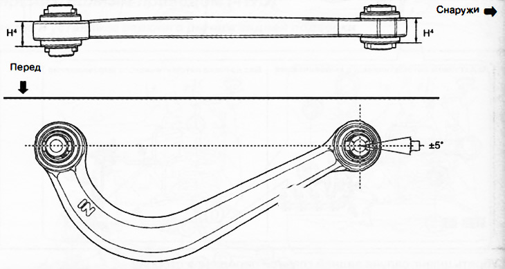
H4: 24.0±0.6 mm
20. Place a timing mark on the new rear upper control arm in the same position as the one on the removed control arm.
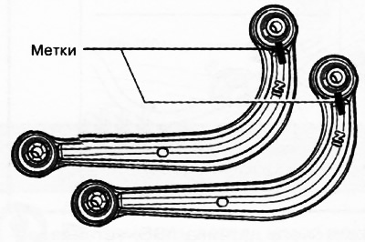
21. Install the upper rear suspension arm.
22. Using a jack, lift the rear subframe assembly and tighten the mounting nuts to a torque of 91-111 Nm.
23. Check and, if necessary, adjust the wheel alignment angles.