
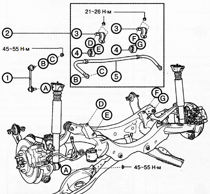
Front wheel drive version (2WD):
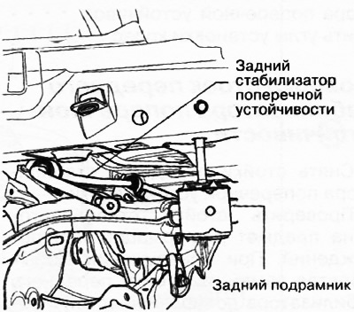
1. Rear anti-roll bar.
2. Rear anti-roll bar assembly.
3. Rear anti-roll bar brackets.
4. Rear anti-roll bar bushings.
5. Rear anti-roll bar.
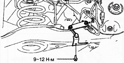
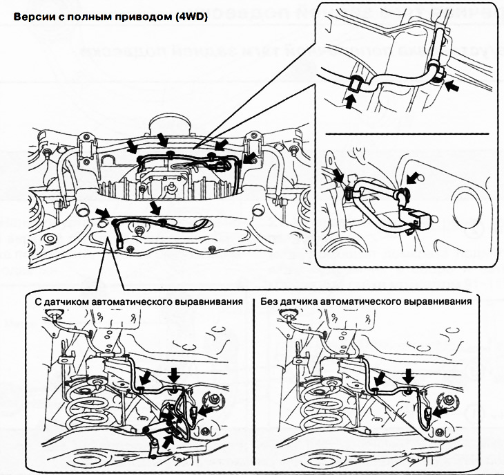
1. Versions with auto level sensor: Working from the left side of the vehicle, disconnect the auto level sensor linkage.
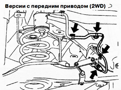
2. Versions with automatic leveling sensor: Disconnect the wiring clamps and connectors mounted on the rear subframe.
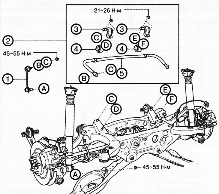
All wheel drive version (4WD):
1. Rear anti-roll bar.
2. Rear anti-roll bar assembly.
3. Rear anti-roll bar brackets.
4. Rear anti-roll bar bushings.
5. Rear anti-roll bar.
Removing the rear anti-roll bar
Attention. Performing the following procedure without first removing the front wheel ABS sensor may result in an accidental open circuit in the wiring harness. Before performing the following procedures, disconnect the front ABS wheel sensor harness (from the side of the drive shaft) and fix the wiring in a suitable place where it will not be erroneously touched when servicing the vehicle.
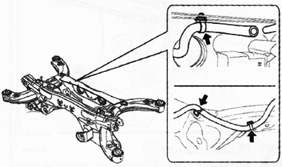
3. Versions with all-wheel drive (4WD): Move the rear final drive breather hose to one side.
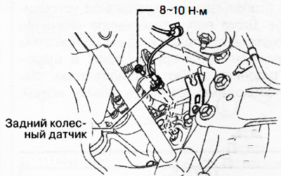
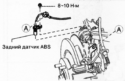
4. Disconnect the ABS rear wheel sensor wiring from the stud and set aside.
Front wheel drive versions (2WD)
Versions with all-wheel drive (4WD)
5. Versions with all-wheel drive (4WD): Remove propshaft.
6. Remove the three-way catalytic converter.
7. Remove the middle part of the exhaust pipe.
8. Remove the rear helical suspension springs.
9. To turn away nuts and to disconnect racks of the stabilizer of cross-section stability.
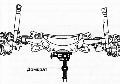
10. Support the rear subframe assembly with a jack and unscrew the fixing nuts.
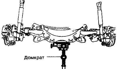
11. Using a jack, lower the rear subframe assembly just enough to allow the rear anti-roll bar assembly to be removed.
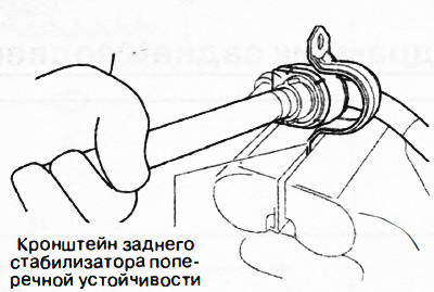
12. Unscrew the mounting bolts and remove the anti-roll bar with brackets from the subframe.
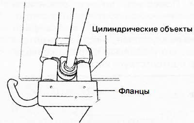
13. Having fixed the flange of the anti-roll bar bracket in a vice, remove the stabilizer bushing from the bracket.
14. Remove the mounting sleeves from the stabilizer bar.
15. Installation is carried out in the reverse order of removal, taking into account the following:
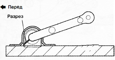
Install the bushings on the front anti-roll bar so that the slits of the bushings point towards the rear of the vehicle.
Install the bracket onto the front anti-roll bar bush by hand. If you cannot manually install the bracket on the hub, use a vise.
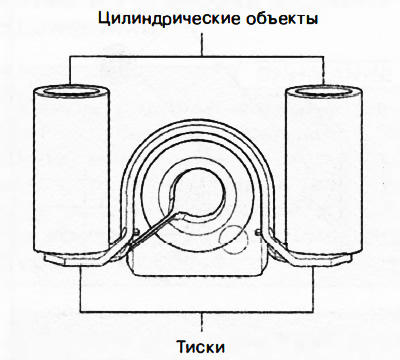
Attention.
- When using a vise to install the front anti-roll bar bracket, the bracket may be deformed.
- Install cylindrical objects as shown in the figure so that the pressure is on the flanges of the front stabilizer bracket, and then install the front anti-roll bar on the stabilizer bushing.
 |  |
When installing the front stabilizer bracket, make sure that the deviation of the relative position of the bracket and bushing corresponds to the range shown in the figure.
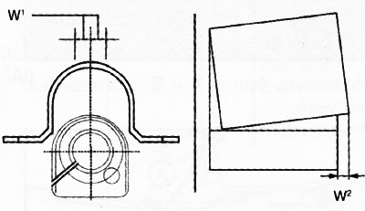
W1: no more than 0.5 mm
W2: no more than 2 mm
After installing the front anti-roll bar bracket, make sure that the protrusion of the bushing from the stabilizer bar bracket is as shown in the figure.
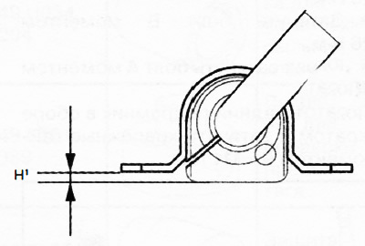
H1: no more than 13 mm
After installing the front stabilizer bracket, make sure that the position deviation between the right and left stabilizer brackets does not exceed the value shown in the figure.
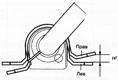
H2: no more than 3 mm.
Place the anti-roll bar with the bushings and brackets installed on a flat surface and check that the value shown in the figure is correct.
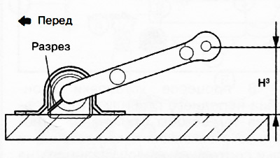
NZ:
- Front wheel drive versions: 66.5-76.5 mm
- All-wheel drive versions: 41.8-51.8 mm
Fit screws A and B as shown in the figure.
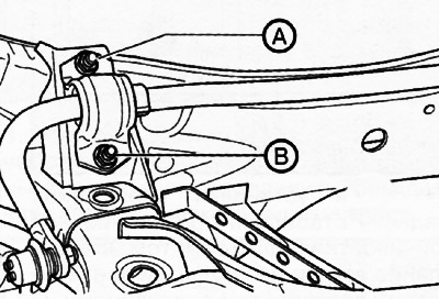
Tighten bolt A to 21-26 Nm.
Tighten bolt B to 21-26 Nm.
Tighten bolt A again to 21-26 Nm.
16. Raise the rear subframe assembly with a jack and tighten the fixing nuts to a torque of 91-111 Nm.
17. After installing the rear anti-roll bar, check the wheel alignment.